
Method for connecting an optical waveguide, embedded in a fibre composite component, to an external optical waveguide

a fiber composite component and optical waveguide technology, applied in the field of connecting optical waveguides, can solve the problems of difficult to realise later expansion of cable form or modular construction thereof, high cost, and high cost of cable form, and achieve the effects of increasing production reliability, precise alignment, and rapid and reliable inspection of end portions

Inactive Publication Date: 2015-05-19
AIRBUS OPERATIONS GMBH
View PDF23 Cites 0 Cited by
  • Summary
  • Abstract
  • Description
  • Claims
  • Application Information

AI Technical Summary

Benefits of technology

[0008]Thus, with the present method it is possible first of all to expose the embedded optical waveguide in a controlled manner and, in a subsequent step, to sever the optical waveguide cleanly. This makes it possible to ensure a reproducible and constant quality of the severed point of the embedded optical waveguide, as a result of which it is possible to produce a reliable connection to the external optical waveguide.
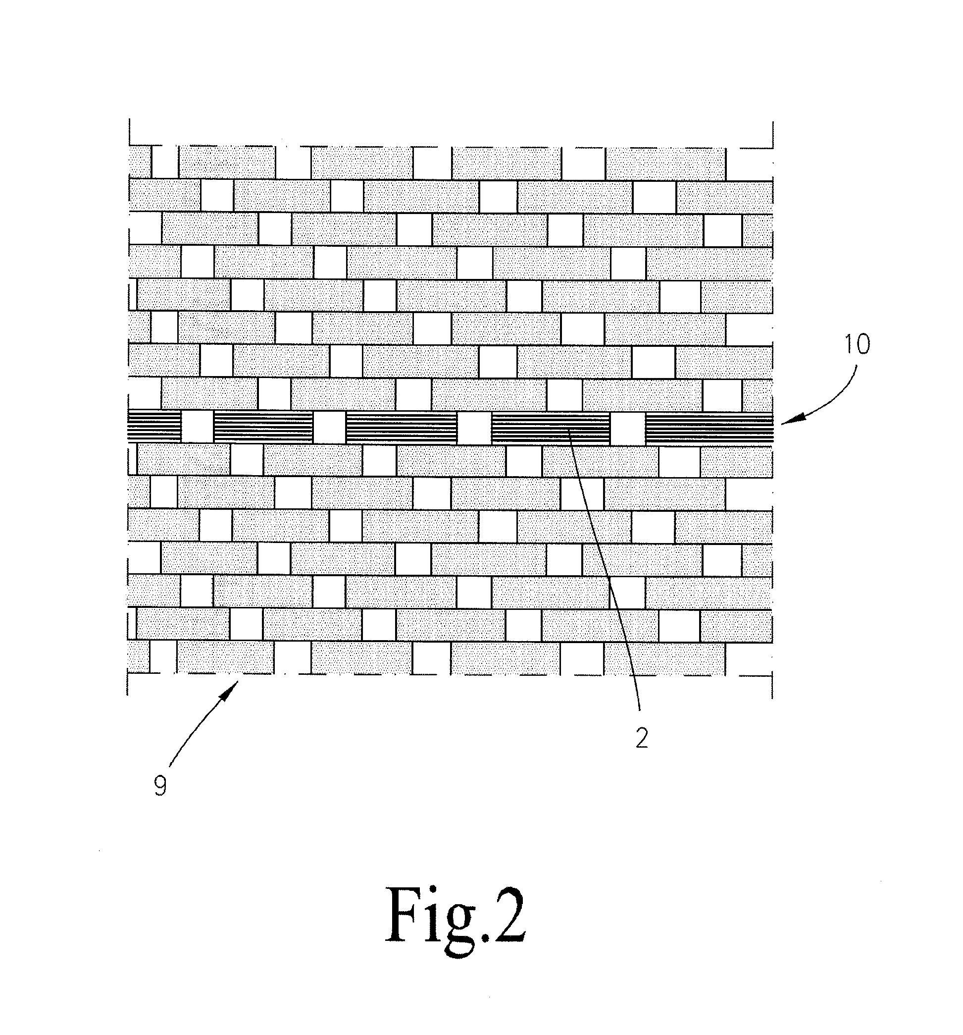
[0020]According to a yet further preferred development of the method according to the invention, the embedded optical waveguide is woven into a laminate layer of the fibre composite component. This makes it possible for the optical waveguide to be processed in a particularly simple manner and simplifies the producibility of the fibre composite component.

Problems solved by technology

Due to the large number of cables which are required and corresponding cable clips, cable forms of aircraft and spacecraft are of an extremely complex construction and are heavy.
Furthermore, a later expansion of the cable form or a modular construction thereof is difficult to realise.
The design process for laying such a cable form is time-consuming, complex and very susceptible to errors.
Customer-specific adaptations and requirements can only be realised where a considerable constructive complexity is involved.
A problem, however, of embedded optical waveguides is the connection thereof to external optical waveguides which are not embedded in the fibre composite component, for example for connecting the embedded optical waveguide to an optical waveguide plug connection.
However, a disadvantage of this arrangement is that it is difficult to sever in a controlled manner the embedded optical transmission means due to the simultaneous severing of the fibre composite component and the first optical transmission means.
This implies an enormous production expense and increases the reject rate.
Therefore, the method cannot be used on an industrial scale.

Method used


Image

  • Method for connecting an optical waveguide, embedded in a fibre composite component, to an external optical waveguide
  • Method for connecting an optical waveguide, embedded in a fibre composite component, to an external optical waveguide
  • Method for connecting an optical waveguide, embedded in a fibre composite component, to an external optical waveguide

Examples


Embodiment Construction

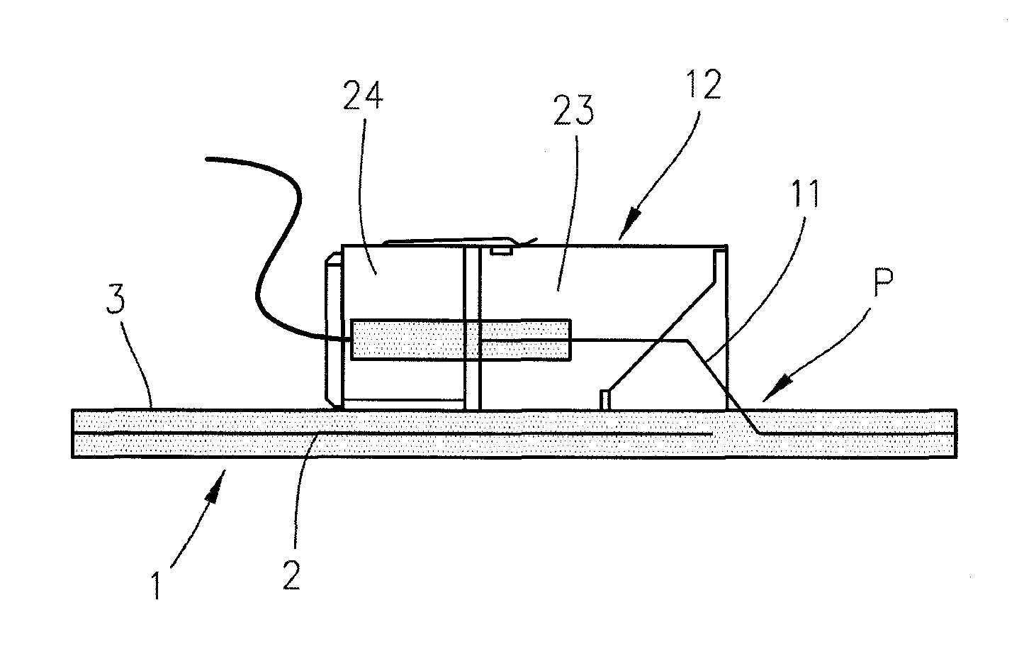
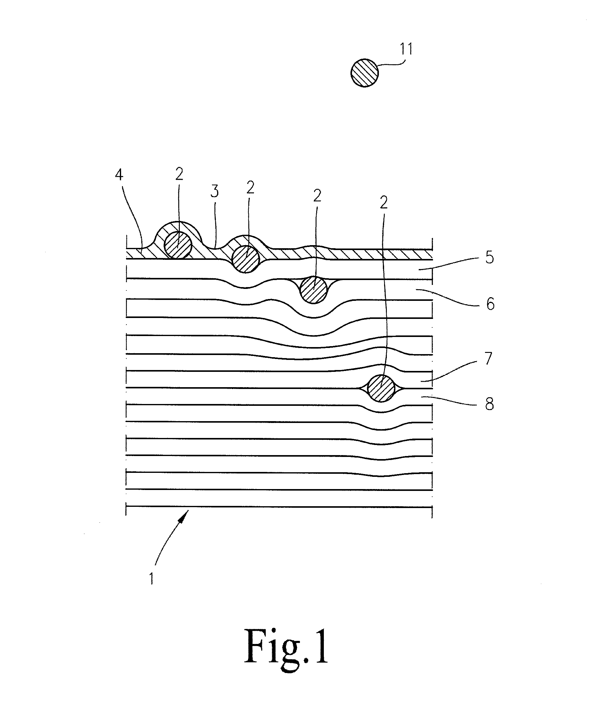
[0033]A preferred embodiment of the present invention is described in the following, while referring simultaneously to FIGS. 1 to 9.

[0034]FIG. 1 illustrates a preferred embodiment of a fibre composite component 1 which is configured, for example, as a structural element 1 of an aircraft and spacecraft. The structural element 1 is configured, for example as a stringer 1, a former 1, a crossbar 1 or the like of the aircraft and spacecraft. The fibre composite component 1 is preferably formed from a carbon fibre-reinforced plastics material (CFRP). Alternatively or additionally, the fibre composite component 1 can be formed from glass fibres, aramid fibres and / or boron fibres or a combination of these materials. The fibre composite component 1 preferably has a large number of laminate plies or laminate layers, only laminate layers 5-8 of which having been provided with a reference numeral. There can be any number of laminate layers 5-8. A laminate layer 5-8 is configured in each case a...


PUM


Abstract

A method for connecting an optical waveguide embedded in a fiber composite component, in particular of an aircraft and spacecraft, to an external optical waveguide, comprising the following steps: ascertaining a path of the embedded optical waveguide in the fiber composite component; determining a nodal position at which the embedded optical waveguide is to be coupled with the external optical waveguide; exposing, at least in portions, the embedded optical waveguide at the nodal position by removing at least part of the fiber composite component around the embedded optical waveguide; severing the exposed embedded optical waveguide; aligning relative to each other an end portion of the severed, embedded optical waveguide and an end portion of the external optical waveguide; and splicing the mutually aligned end portions of the optical waveguides.

Description

CROSS-REFERENCES TO RELATED APPLICATIONS[0001]This application claims the benefit of the U.S. Provisional Application No. 61 / 372,316, filed on Aug. 10, 2010, and of the German patent application No. 10 2010 039 153.0 filed on Aug. 10, 2010, the entire disclosures of which are incorporated herein by way of reference.FIELD OF THE INVENTION[0002]The present invention relates to a method for connecting an optical waveguide, embedded in a fibre composite component, in particular of an aircraft and spacecraft, to an external optical waveguide.[0003]Although the present invention can be applied to any fibre composite components, it will be described with respect to a fibre composite component of an aircraft and spacecraft.BACKGROUND OF THE INVENTION[0004]Due to the large number of cables which are required and corresponding cable clips, cable forms of aircraft and spacecraft are of an extremely complex construction and are heavy. Furthermore, a later expansion of the cable form or a modula...

Claims


Application Information

Patent Timeline
Patent Type & Authority Patents(United States)
IPC IPC(8): G02B6/255G02B6/36G02B6/38
CPCG02B6/2553G02B6/3608G02B6/3664G02B6/3897G02B6/255G02B6/2551
Inventor BROWNJOHN, NICHOLAS E.OSTERNACK, STEFAN
Owner AIRBUS OPERATIONS GMBH
Learn More