
High-power medium-voltage drive power cell having power elements disposed on both sides of base plate

a technology of power elements and base plates, applied in the direction of power conversion systems, ac-ac conversion, electrical apparatus construction details, etc., can solve the problems of high system cost, large volume and heavy weight of aluminum extrusion heat sinks, and inconvenience of electrical connections between power elements and capacitors, etc., to improve improve the heat dissipation efficiency of the system, and improve the effect of thermal conductan

Active Publication Date: 2015-04-28
DELTA ELECTRONICS (SHANGHAI) CO LTD
View PDF13 Cites 9 Cited by
  • Summary
  • Abstract
  • Description
  • Claims
  • Application Information

AI Technical Summary

Benefits of technology

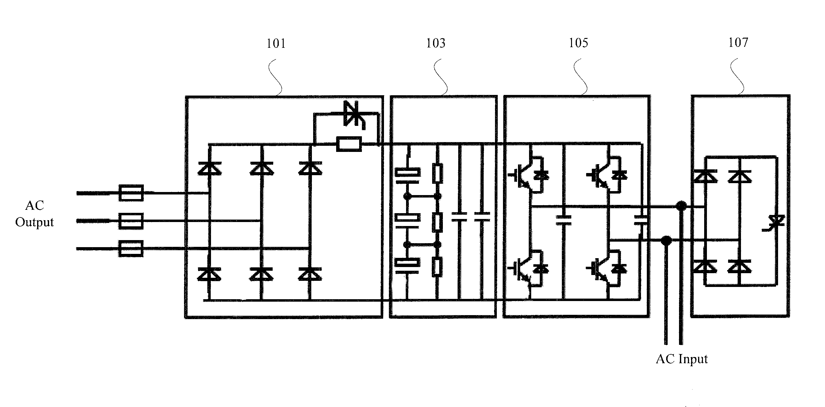
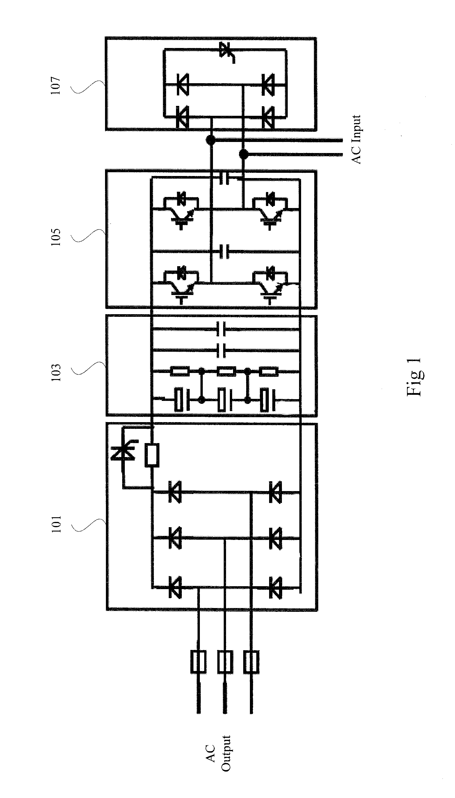
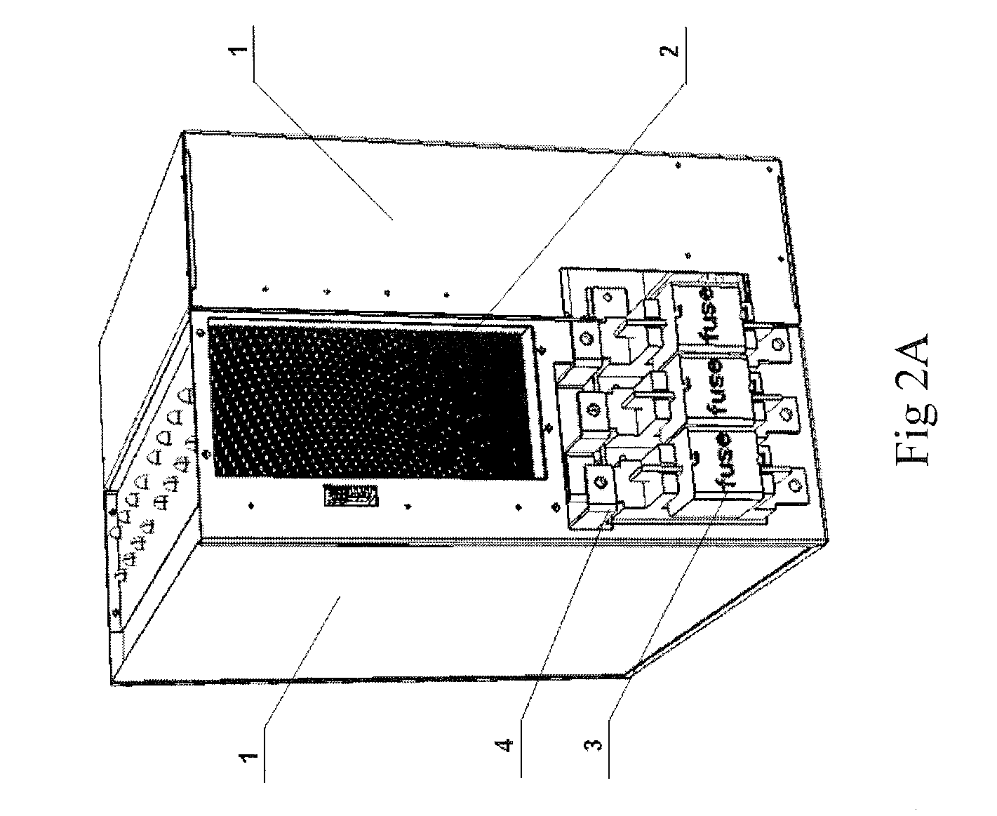
The present invention provides a high-power medium-voltage drive power cell that has excellent heat dissipation efficiency and a compact structure. The power elements (rectifier module, inverter module and bypass module) are arranged at two sides of the heat pipe heat sink, which facilitates fast heat dissipation and reduces the operation temperatures of the power elements. By using the capacitor subunit and IGBT inverter bridge that are electrically connected via buses, the circuit stray inductances are significantly reduced. The power cell can be easily disassembled into two independent subunits, which are of substantially equal weight and connected only by screws. This makes the power cell more convenient for manufacturing, installation, maintenance and dismantling.

Problems solved by technology

This structure causes high heat dissipation requirements.
When a large-scale heat sink is used, the distance between modules is relative large, and the layout is non-compact, which causes inconvenience for the electrical connections between the power elements and capacitors.
Furthermore, the aluminum extrusion heat sink has a large volume and a heavy weight, and a high system cost.

Method used


Image

  • High-power medium-voltage drive power cell having power elements disposed on both sides of base plate
  • High-power medium-voltage drive power cell having power elements disposed on both sides of base plate
  • High-power medium-voltage drive power cell having power elements disposed on both sides of base plate

Examples


Embodiment Construction

[0023]Specific embodiments of the present invention are further described in detail below with reference to the accompanying drawings.

[0024]In order to make the description of the present invention more detailed and more comprehensive, various embodiments are described below with reference to the accompanying drawings. The same reference numbers are used in the drawings referring to the same or like elements. However, the embodiments described are not intended to limit the present invention. Moreover, it is not intended for the description of operation to limit the scope of implementation. Any device with equivalent functions that is produced from a structure formed by a recombination of elements shall fall within the scope of the present invention.

[0025]The drawings are only illustrative and are not drawn according to actual size. Additionally, well-known elements and steps are not described in the embodiments to avoid causing unnecessary limitations to the present invention.

[0026]...


PUM


Abstract

The present invention provides a high-power medium-voltage drive power cell, which comprises: a rectifier module for rectifying the three-phase AC input voltage to get a DC voltage; an IGBT (Insulated Gate Bipolar Transistor) inverter bridge connected to capacitors for converting the DC voltage into an AC voltage of which the frequency, the amplitude and the phase are adjustable; a bypass module connected to the IGBT inverter bridge for providing the bypass function when the IGBT inverter bridge works in an abnormal state; and a heat pipe heat sink having a base plate on both sides of which power elements of the high-power medium-voltage drive power cell are disposed.

Description

RELATED APPLICATIONS[0001]This application claims priority to Chinese Application Serial Number 201110318870.X, filed Oct. 19, 2011, which is herein incorporated by reference.BACKGROUND[0002]1. Field of Invention[0003]The present invention relates to a variable frequency modulation technique with the power electronic devices. More particularly, the present invention relates to a high-power medium-voltage drive power cell.[0004]2. Description of Related Art[0005]With the rapid development of the modern power electronic technology and microelectronic technology, the medium-voltage high-power variable frequency control device has been used more and more widely, such as various wind generators, water pumps, compressors, rolling machines used in various industries such as petrochemical engineering, municipal water supply, ferrous metallurgy and electric energy.[0006]In the prior art, a power cell with relatively independent functions is an important part of a cascaded medium-voltage driv...

Claims


Application Information

Patent Timeline
Patent Type & Authority Patents(United States)
IPC IPC(8): H02M5/45H02M1/32H02M5/458H02M7/00H05K7/20
CPCH02M1/32H05K7/20936H02M5/458H02M7/003H02M2001/325H02M1/325
Inventor TONG, AI-XINGCHANG, YU-MINGGAN, HONG-JIANMA, SHAO-CAIYING, JIAN-PING
Owner DELTA ELECTRONICS (SHANGHAI) CO LTD
Learn More