
Electric power steering apparatus

a technology of electric power steering and electric motor, which is applied in the direction of electric steering, power driven steering, vehicle components, etc., can solve the problems of thermal interference between heat transfer passages from respective heat sources, deterioration of heat dissipation efficiency, etc., and achieve the effect of preventing heat interference and obtaining heat dissipation efficiency

Inactive Publication Date: 2015-03-24
HITACHI ASTEMO LTD
View PDF4 Cites 5 Cited by
  • Summary
  • Abstract
  • Description
  • Claims
  • Application Information

AI Technical Summary

Benefits of technology

The present invention is about an electric power steering apparatus that has a heat guide part to improve heat dissipation efficiency. The heat guide part helps to quickly guide heat from heat sources to the heat radiating means, which prevents heat interference and increases efficiency in heat dissipation.

Problems solved by technology

In such a case, however, thermal interference may occur between heat transfer passages from the respective heat sources.
This results in a deterioration of heat dissipation efficiency.

Method used


Image

  • Electric power steering apparatus
  • Electric power steering apparatus
  • Electric power steering apparatus

Examples


first embodiment

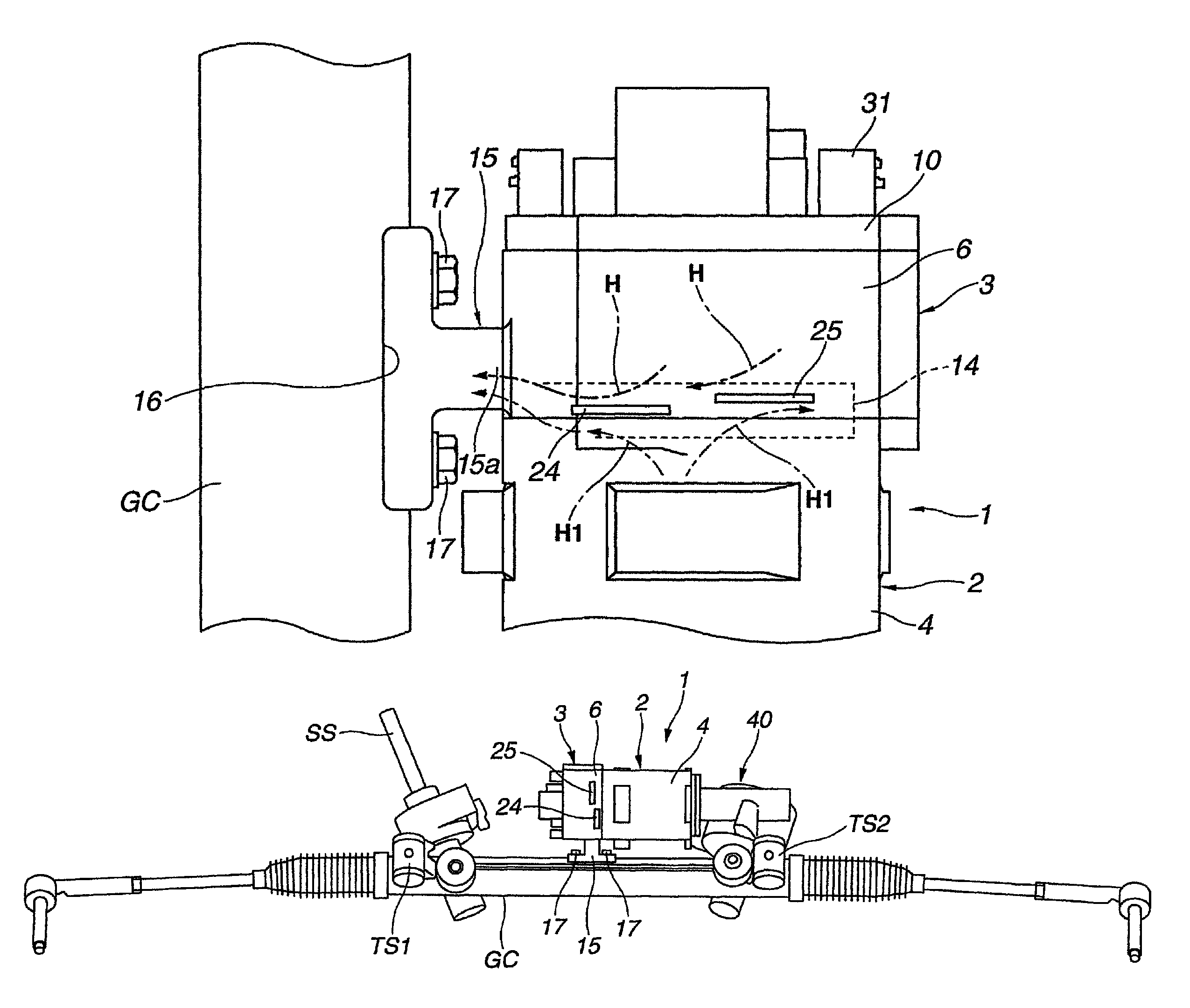
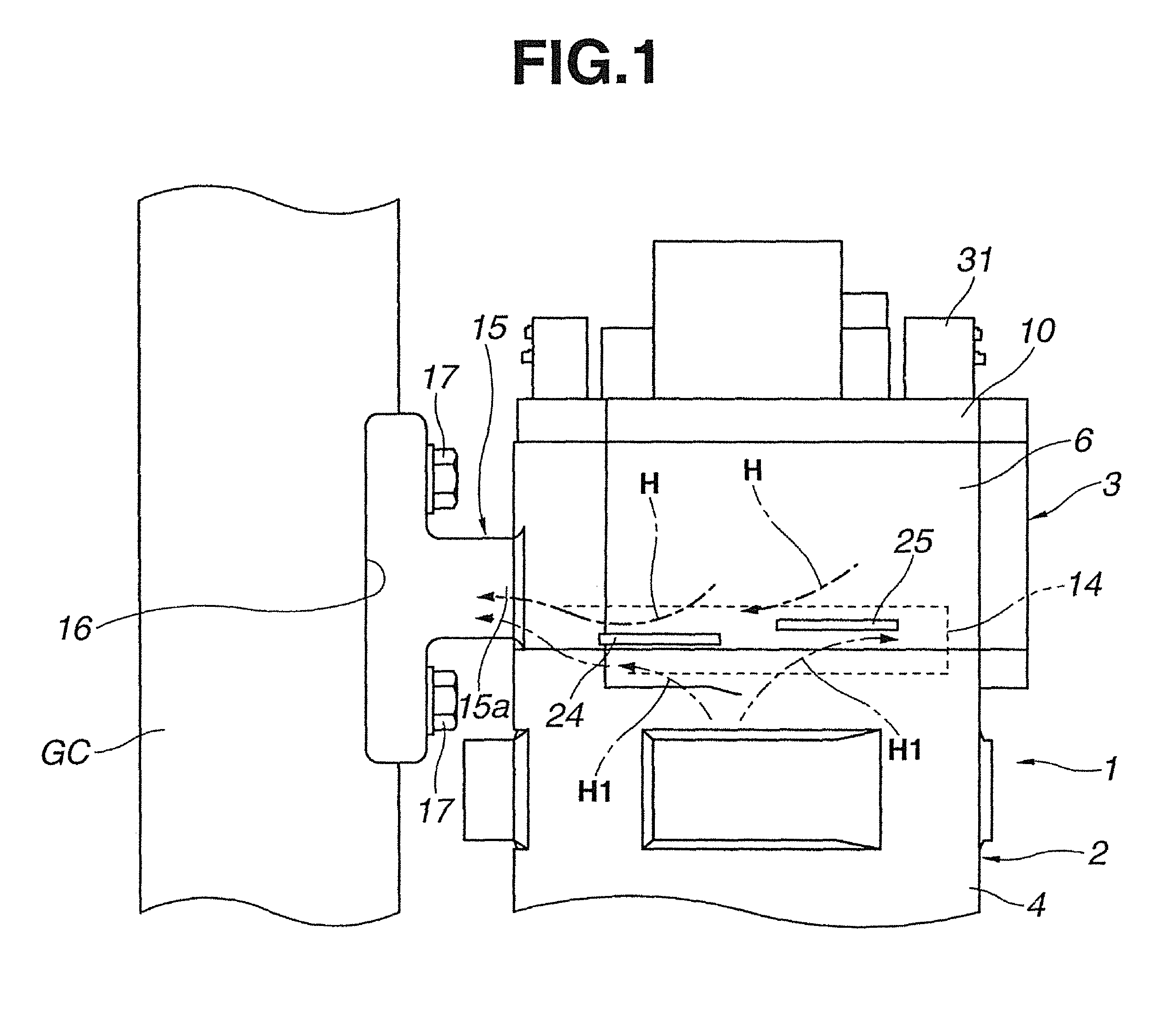
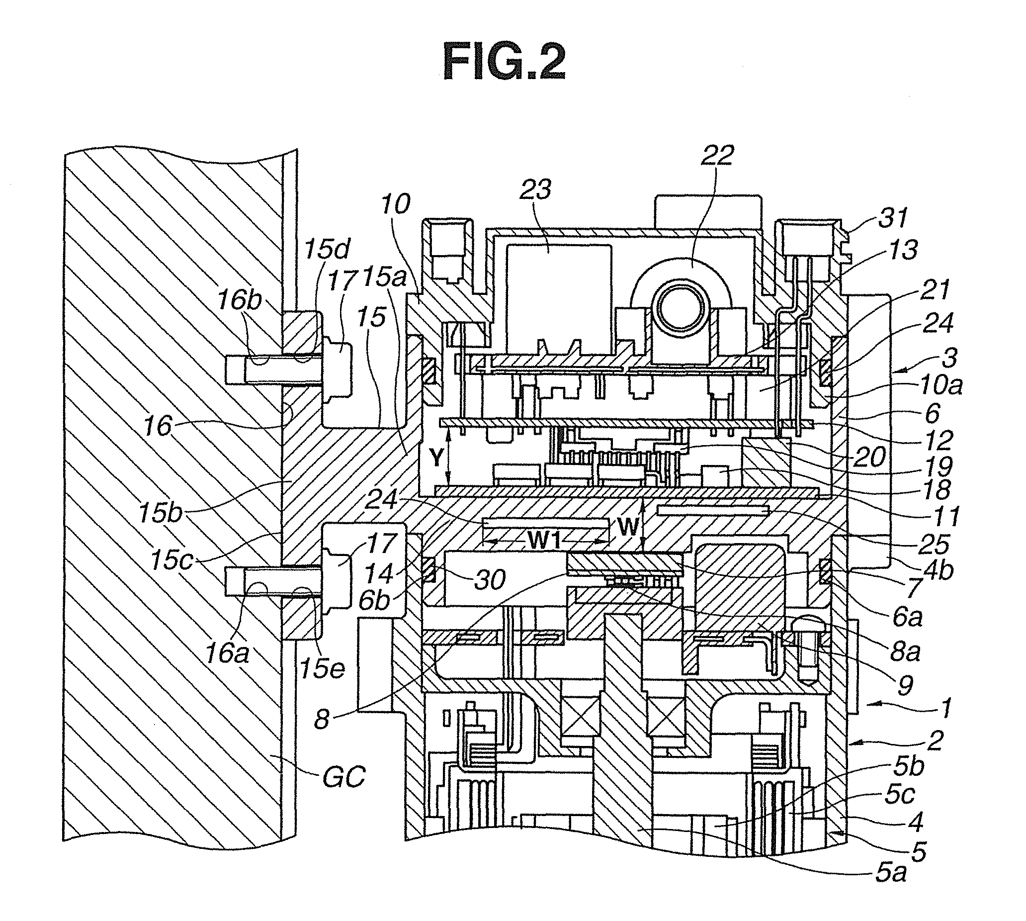
[0015]As shown in FIG. 3, an electric power steering apparatus for an automotive vehicle according to the first embodiment of the present invention is disposed adjacent to a steering shaft SS of the vehicle and is provided with a gear case GC, a rack pinion gear unit, an electric actuator 1, a bracket 15 (as a metal joint part) and first and second torque sensors TS1 and TS2. The gear case GC is made of a metal material such as iron and is fixed to a base end portion of the steering shaft SS. Although not specifically shown in the drawings, the rack pinion gear unit is accommodated in the gear case GC. In the first embodiment, the gear case GC and the rack pinion gear unit constitute a driving torque transmission mechanism. The electric actuator 1 is coupled to a side portion of the gear case GC through the bracket 15 so as to assist rotation of the steering shaft SS. The first torque sensor TS1 is attached to one end portion of the gear case GC (adjacent to the base end of the stee...

second embodiment

[0053]An electric power steering apparatus for an automotive vehicle according to the second embodiment of the present invention is structurally similar to that according to the first embodiment, except for the structure of the heat guide part.

[0054]More specifically, the heat guide part includes not only guide slits 24 and 25 but also a link slit 26 extending between the guide slits 24 and 25 as shown in FIGS. 4 and 5. (The guide slits 24 and 25 and the link slit 26 are combined into one slit.) In the second embodiment, the guide slits 24 and 25 are in the same arrangement and dimensions (such thickness and width W1) as those in the first embodiment. The link slit 26 is formed through the bottom wall 14 substantially in parallel with the guide slits 24 and 25 and inclinedly in such a manner that the link slit 26 is connected at one end side thereof to an end side of the guide slit 15 closer to the bracket 15 and at the other end side thereof to an end side of the guide slit 24 fart...


PUM


Abstract

An electric power steering apparatus includes an electric motor, a drive torque transmission mechanism for converting a rotation of the electric motor to a linear movement and transmitting the linear movement to vehicle wheels, first and second circuit boards mounting electronic components to process a motor control command and drive the electric motor based on the motor control command, a metal control housing accommodating therein the first and second circuit boards and coupled at an outer surface thereof to the drive torque transmission mechanism, a heat transfer part located inside the control housing so as to receive heat from the respective circuit boards and a heat guide part extending from the outer surface of the control housing to the inside of the heat transfer member so as to guide the heat transferred to the heat transfer part in a direction toward the drive torque transmission mechanism.

Description

BACKGROUND OF THE INVENTION[0001]The present invention relates to an improvement in an electric power steering apparatus for an automotive vehicle.[0002]As is well known, an electric power steering apparatus for an automotive vehicle has an electric actuator such as an electric motor to assist driver's steering operation by a rotational driving force of the electric actuator.[0003]Japanese Unexamined Patent Application Publication (Translation of PCT Application) No. 2011-189868 discloses one type of electric actuator for use in such an electric power steering apparatus, in which a motor control circuit board and an inverter power module (circuit board) are stacked and incorporated into a control unit. In this control unit, heat generating electronic components such as CPU for command processing, IC (ASIC) for power supply control, semiconductor switch (FETMOS) for motor control, motor relay (power supply relay) for fail safe control etc. are mounted on the circuit boards. There is ...

Claims


Application Information

Patent Timeline
Patent Type & Authority Patents(United States)
IPC IPC(8): B62D5/04
CPCB62D5/0406B62D5/0409B62D5/00B62D5/04H05K9/00
Inventor HAGIWARA, KATSUMASAMOTODA, HARUAKI
Owner HITACHI ASTEMO LTD
Learn More