
Partially-reduced iron producing method and partially-reduced iron producing apparatus

a technology of iron producing apparatus and iron production method, which is applied in the direction of lighting and heating apparatus, manufacturing converters, furnaces, etc., can solve the problems of low degree of reduction, inability to achieve high degree of reduction, and difficulty in operation, so as to reduce the consumption of carbon material and carbon dioxide, suppress the reoxidation, and reduce the effect of the iron producing process

Inactive Publication Date: 2015-02-24
PRIMETALS TECHNOLOGIES JAPAN LTD
View PDF7 Cites 3 Cited by
  • Summary
  • Abstract
  • Description
  • Claims
  • Application Information

AI Technical Summary

Benefits of technology

This patent describes a process for producing partially-reduced iron by heating raw-material pellets using the combustion heat of ignition carbon material. The flammable volatile component is generated from the reduction carbon material in the raw-material pellets and combusts, causing the temperature of the pellets to rise and promoting a reduction reaction. Carbon monoxide gas is produced and then combined with oxygen-containing gas to further increase the concentration near the raw-material pellets. The combustion heat is used to form a temperature range where carbon dioxide emissions are reduced. The reducing process cools the raw-material pellets and prevents reoxidation, resulting in high-quality partially-reduced iron. This process achieves reduced carbon material consumption and carbon dioxide emissions and produces high-quality partially-reduced iron.

Problems solved by technology

However, the technique described in Patent Literature 1 has the following problems and a partially-reduced iron with a high degree of reduction cannot be obtained.
Moreover, even if the reduction proceeds, the carbon composite pellets are reoxidized by air and thus the degree of reduction does not improve at all.
Moreover, since a high temperature state is maintained, a molten slag is excessively generated and an operation may thereby become difficult in some cases.
However, the amount of remaining carbon is small and the degree of metallization is low.
However, since the amount of flammable components is small with respect to the amount of the entire exhaust gas, a supplementary fuel is additionally required.

Method used


Image

  • Partially-reduced iron producing method and partially-reduced iron producing apparatus
  • Partially-reduced iron producing method and partially-reduced iron producing apparatus
  • Partially-reduced iron producing method and partially-reduced iron producing apparatus

Examples


Embodiment Construction

[0023]Descriptions are given below of a mode for carrying out a partially-reduced iron producing method and a partially-reduced iron producing apparatus of the present invention.

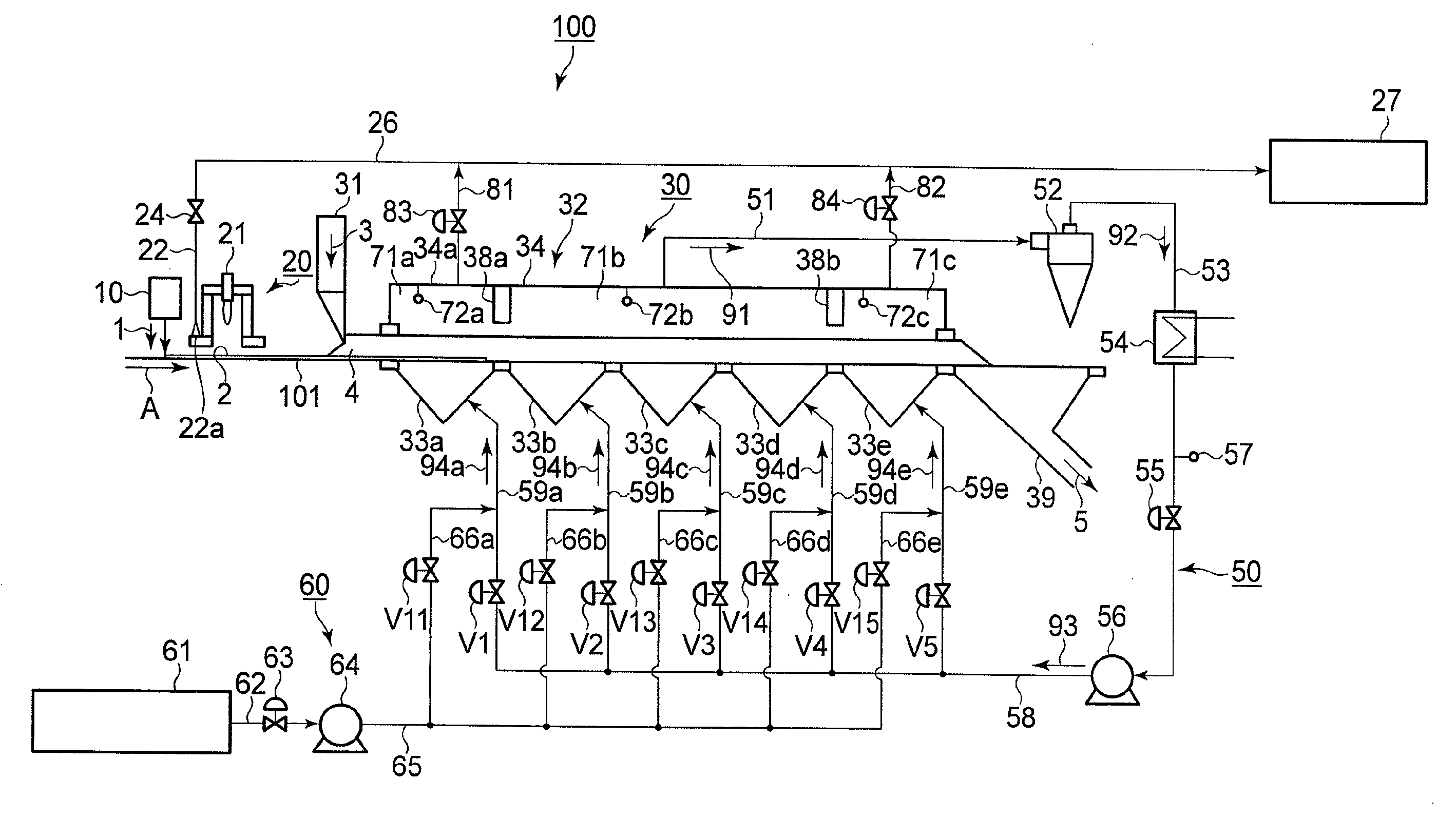
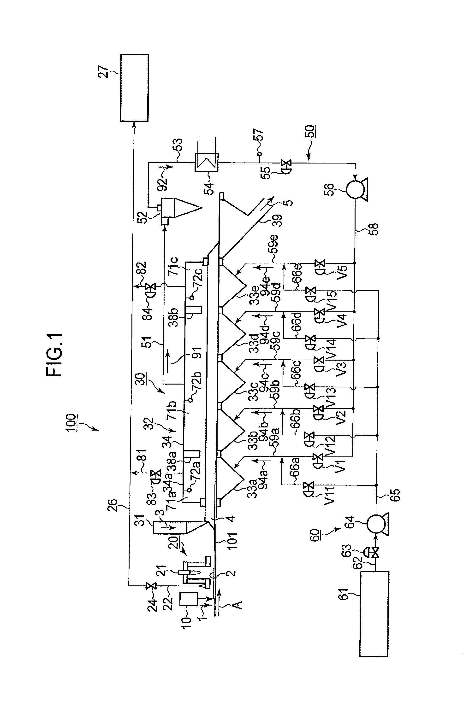
[0024]One embodiment of the partially-reduced iron producing method and the partially-reduced iron producing apparatus of the present invention is described with reference to FIGS. 1 to 3. In FIG. 1, the arrow A shows a travelling direction of a grate.

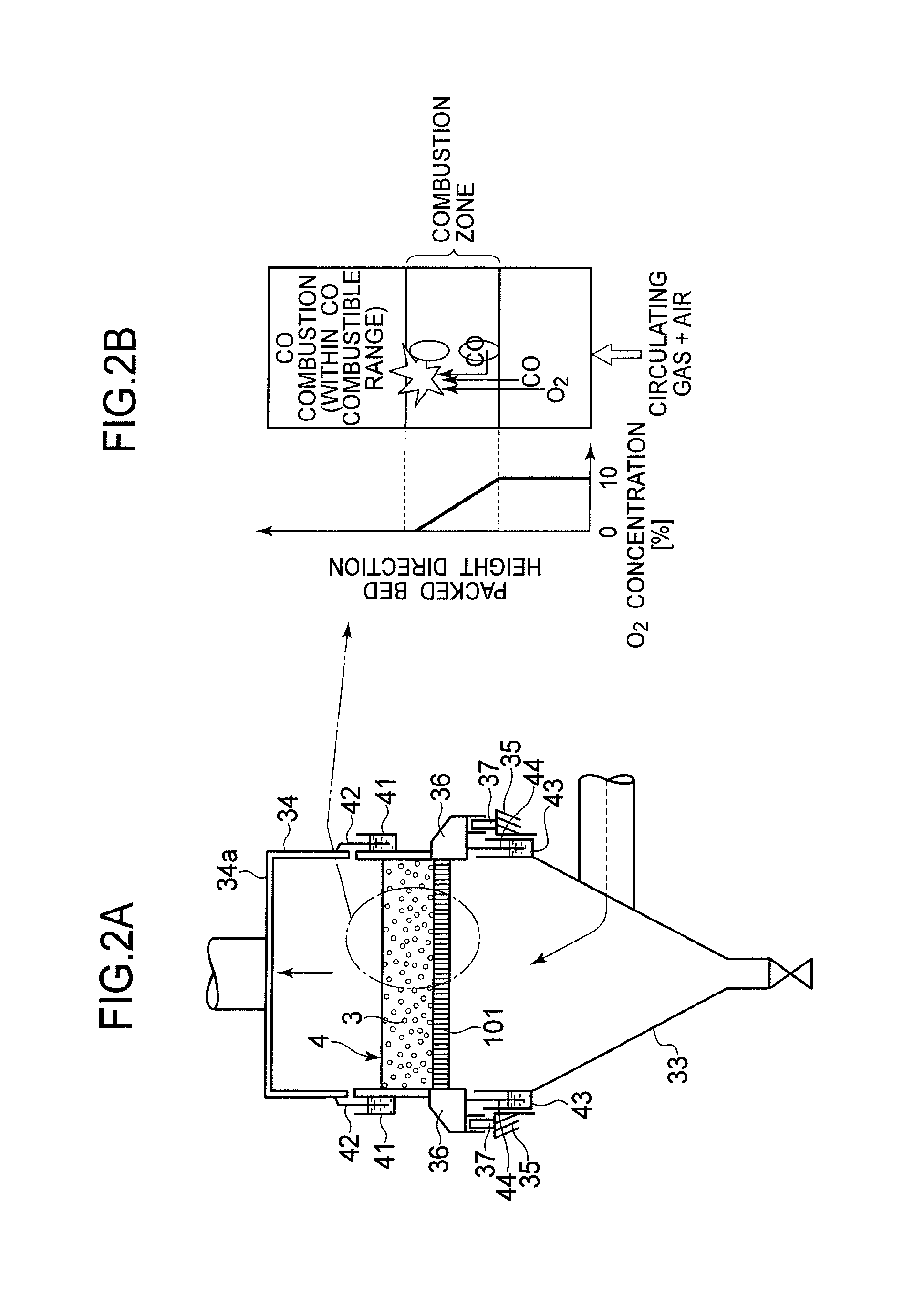
[0025]As shown in FIGS. 1, 2A, and 2B, the partially-reduced iron producing apparatus of the present invention includes a grate reduction furnace 100 of an upward suction type. The grate reduction furnace 100 includes an ignition coal supplying device 10, a combustion device 20, and a reduction furnace (partial reduction furnace) 30. These components are arranged from upstream in the travelling direction of a grate (endless grate) 101 in the order of description.

[0026]The ignition coal supplying device 10 is a device which supplies an ignition coal (ignition ca...


PUM

PropertyMeasurementUnit
laying heightaaaaaaaaaa
heightaaaaaaaaaa

Abstract

A reduction furnace includes a pellet material supplying device forming on a grate an ignition carbon material layer having a predetermined height; an ignition device; and an exhaust gas circulation device supplying an oxygen-containing gas comprising circulated exhaust gas mixed with air, to a packed bed of the pellets heated by a combustion heat of the ignition carbon material layer. A partially-reduced iron is produced by thermally reducing the pellets through a combustion region for the ignition carbon material layer and a heating region, the combustion region formed upstream in a travelling direction of the grate by supplying a gas having a high oxygen concentration, the heating region formed downstream of the combustion region by supplying a gas having a low oxygen concentration.

Description

TECHNICAL FIELD[0001]The present invention relates to a partially-reduced iron producing method and a partially-reduced iron producing apparatus for producing a partially-reduced iron by reducing agglomerates containing iron oxides.BACKGROUND ART[0002]For example, Patent Literature 1 listed below discloses a conventional technique of producing a partially-reduced iron by packing carbon composite pellets on a moving grate and thermally reducing the pellets, the carbon composite pellets not being coated with a carbon material for combustion.[0003]However, the technique described in Patent Literature 1 has the following problems and a partially-reduced iron with a high degree of reduction cannot be obtained.[0004](1) After being dried, the carbon composite pellets are ignited with a gas torch and air is made to flow therethrough to combust and heat the carbon composite pellets. Accordingly, a portion of a packed bed of the carbon composite pellets on a side into which air flows keeps o...

Claims


Application Information

Patent Timeline
Patent Type & Authority Patents(United States)
IPC IPC(8): C22B1/02C21B11/10F27D17/00C21B13/00C21B13/10C21B13/14C21C5/52F27B9/24F27B9/30
CPCC22B1/02C21B11/10F27D17/002C21B13/0046C21B13/10C21B13/143F27B9/30C21C5/5229F27B9/243F27B2009/3027Y02P10/20
Inventor KAMIKAWA, SUSUMUNAKAJIMASATO, KEIICHIPHAM, KHANHSON
Owner PRIMETALS TECHNOLOGIES JAPAN LTD
Learn More