
High-power laser using thulium-doped fiber amplifier and frequency quadrupling for blue output

a fiber amplifier and high-power technology, applied in the field of optical waveguides, can solve the problems of reducing the loss of guided desired light, inefficient devices, and high cost of lasers that emit high-power blue-green or blue light in the 450-500-nm region, and achieving the effects of low cost, simple setup and operation, and compact footprin

Active Publication Date: 2015-02-10
LOCKHEED MARTIN CORP
View PDF50 Cites 50 Cited by
  • Summary
  • Abstract
  • Description
  • Claims
  • Application Information

AI Technical Summary

Benefits of technology

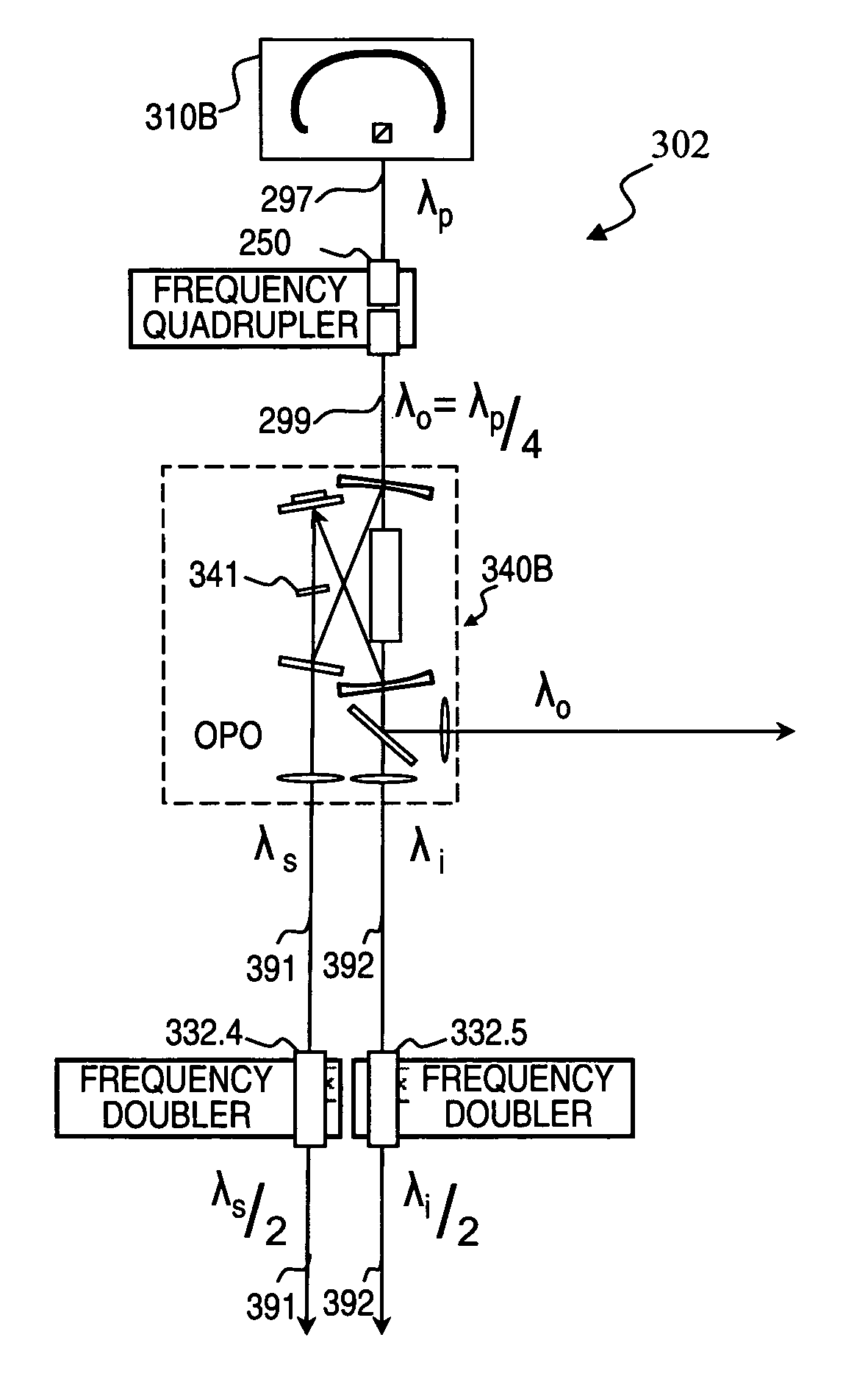
The present invention offers laser architectures that can operate in Q-switched, cavity-dumping, or hybrid Q-switched / cavity-dumping modes for efficient lasing. The initial or seed laser is designed as a unidirectional ring cavity, which minimizes pulse-to-pulse amplitude / temporal instabilities and feedback effects. The Q-switched mode includes a low-core rare-earth-doped fiber, an electro-optic switch, and an output coupler, while the cavity-dumping mode includes a small-aperture rubidium titanyl phosphate (RTP) Pockels cell. The invention offers low cost, compact footprint, and simple setup and operation.

Problems solved by technology

Conventional state-of-the-art lasers for outputting high-power blue-green or blue light having wavelengths in the 450-500-nm region are very costly, inefficient, and fragile.
Prior-art devices for generating these wavelengths typically require many nonlinear conversion steps, including use of a tunable laser or optical parametric oscillator.
This leads to decreased losses of guided desired light as well as to decreased losses through emission of undesired light, compared to devices of the prior art.

Method used


Image

  • High-power laser using thulium-doped fiber amplifier and frequency quadrupling for blue output
  • High-power laser using thulium-doped fiber amplifier and frequency quadrupling for blue output
  • High-power laser using thulium-doped fiber amplifier and frequency quadrupling for blue output

Examples


Embodiment Construction

[0050]Although the following detailed description contains many specifics for the purpose of illustration, a person of ordinary skill in the art will appreciate that many variations and alterations to the following details are within the scope of the invention. Accordingly, the following preferred embodiments of the invention are set forth without any loss of generality to, and without imposing limitations upon the claimed invention. Further, in the following detailed description of the preferred embodiments, reference is made to the accompanying drawings that form a part hereof, and in which are shown by way of illustration specific embodiments in which the invention may be practiced. It is understood that other embodiments may be utilized and structural changes may be made without departing from the scope of the present invention.

[0051]The leading digit(s) of reference numbers appearing in the Figures generally corresponds to the Figure number in which that component is first intr...


PUM


Abstract

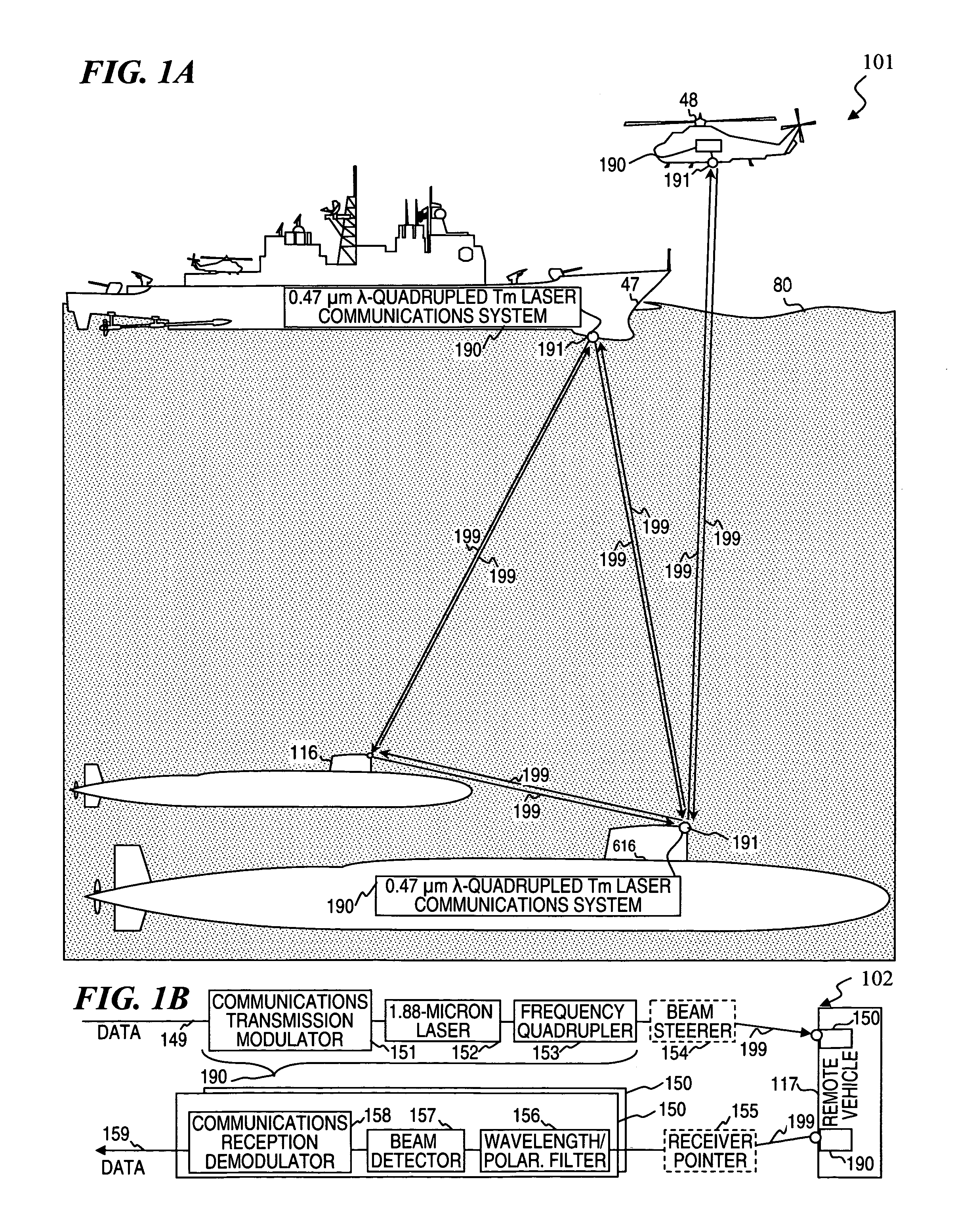
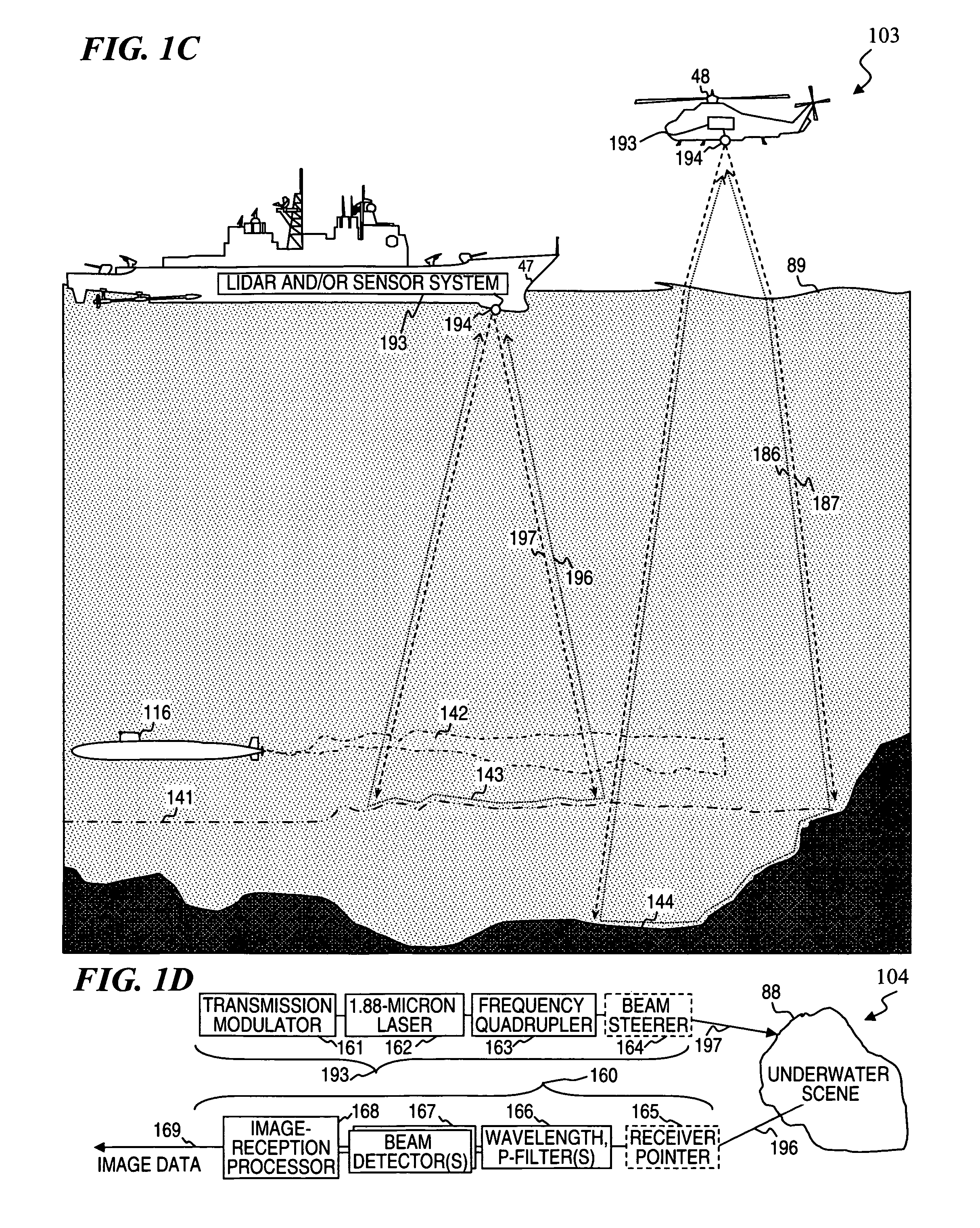
An apparatus, method and associated fiber-laser architectures for high-power pulsed operation and pumping wavelength-conversion devices. Some embodiments generate blue laser light by frequency quadrupling infrared (IR) light from Tm-doped gain fiber using non-linear wavelength conversion. Some embodiments use a fiber MOPA configuration to amplify a seed signal from a semiconductor laser or ring fiber laser. Some embodiments use the frequency-quadrupled blue light for underwater communications, imaging, and / or object and anomaly detection. Some embodiments amplitude modulate the IR seed signal to encode communication data sent to or from a submarine once the modulated light has its wavelength quartered. Other embodiments transmit blue-light pulses in a scanned pattern and detect scattered light to measure distances to objects in a raster-scanned underwater volume, which in turn are used to generate a data structure representing a three-dimensional rendition of the underwater scene being imaged for viewing by a person or for other software analysis.

Description

CROSS-REFERENCE TO RELATED APPLICATIONS[0001]This application claims priority benefit under 35 U.S.C. §119(e) to U.S. Provisional Patent Application No. 61 / 198,405 filed on Oct. 13, 2009, titled “HIGH-POWER LASER USING THULIUM-DOPED FIBER AMPLIFIER AND FREQUENCY QUADRUPLING FOR BLUE OUTPUT,” which is incorporated herein by reference in its entirety.[0002]This invention is related to:[0003]U.S. Provisional Patent Application Ser. No. 60 / 896,265 filed on Mar. 21, 2007, titled “HIGH-POWER, PULSED RING FIBER OSCILLATOR”;[0004]U.S. patent application Ser. No. 12 / 053,551 filed on Mar. 21, 2008, titled “HIGH-POWER, PULSED RING FIBER OSCILLATOR AND METHOD” which issued as U.S. Pat. No. 7,876,803 on Jan. 25, 2011);[0005]U.S. patent application Ser. No. 12 / 050,937 filed Mar. 18, 2008, titled “A METHOD AND MULTIPLE-MODE DEVICE FOR HIGH-POWER SHORT-PULSE-LASER ABLATION AND CW CAUTERIZATION OF BODILY TISSUES” which issued as U.S. Pat. No. 8,202,268 on Jun. 19, 2012);[0006]U.S. Pat. No. 7,429,734...

Claims


Application Information

Patent Timeline
IPC IPC(8): H01S3/30
CPCH01S3/06754H01S3/06791H01S3/08027H01S3/094003H01S3/1616H01S3/0078H01S3/0092H01S3/115G01B11/28G01B11/2518H01S3/107G01S7/4813H04B10/808H04B10/80
Inventor MEAD, ROY D.MINELLY, JOHN D.HONEA, ERIC C.
Owner LOCKHEED MARTIN CORP
Learn More