
Synthetic opal and photonic crystal

a technology of photonic crystals and synthetic opals, applied in the field of photonics and microfabrication, can solve the problems of changing the stability of electrolyte and appropriate adjustments, and achieve the effects of high melting point, low vapor pressure and high vapor pressure material

Inactive Publication Date: 2015-01-20
PRACTICAL TECH
View PDF16 Cites 11 Cited by
  • Summary
  • Abstract
  • Description
  • Claims
  • Application Information

AI Technical Summary

Benefits of technology

This patent describes a method for creating high-quality opal structures and inverse opal structures using colloidal suspensions of polystyrene spheres. The method involves simultaneously sedimenting the spheres under the influence of both electric and magnetic fields to form a crystal structure. A damped oscillatory magnetic field is applied to remove defects during accelerated sedimentation. The resulting crystal has both high quality and high speed of formation. The method is cost-effective and environmentally friendly. The patent also describes the use of electrodeposited metal and the advantages and disadvantages of different methods for fabricating opal and inverse opal structures. The technical effects of this patent include the creation of low-cost, high-quality opal and inverse opal structures that can be used for various applications such as photonic crystals, chemical and mechanical functions, thermal and acoustic insulators, and synthetic gemstones.

Problems solved by technology

Another disadvantage is that the electrolyte changes the colloid stability and appropriate adjustments must be made.

Method used


Image

  • Synthetic opal and photonic crystal
  • Synthetic opal and photonic crystal
  • Synthetic opal and photonic crystal

Examples


Embodiment Construction

[0021]Embodiments of the present invention and their advantages are best understood by referring to FIGS. 1 through 3 of the drawings, in which like numerals refer to like parts.

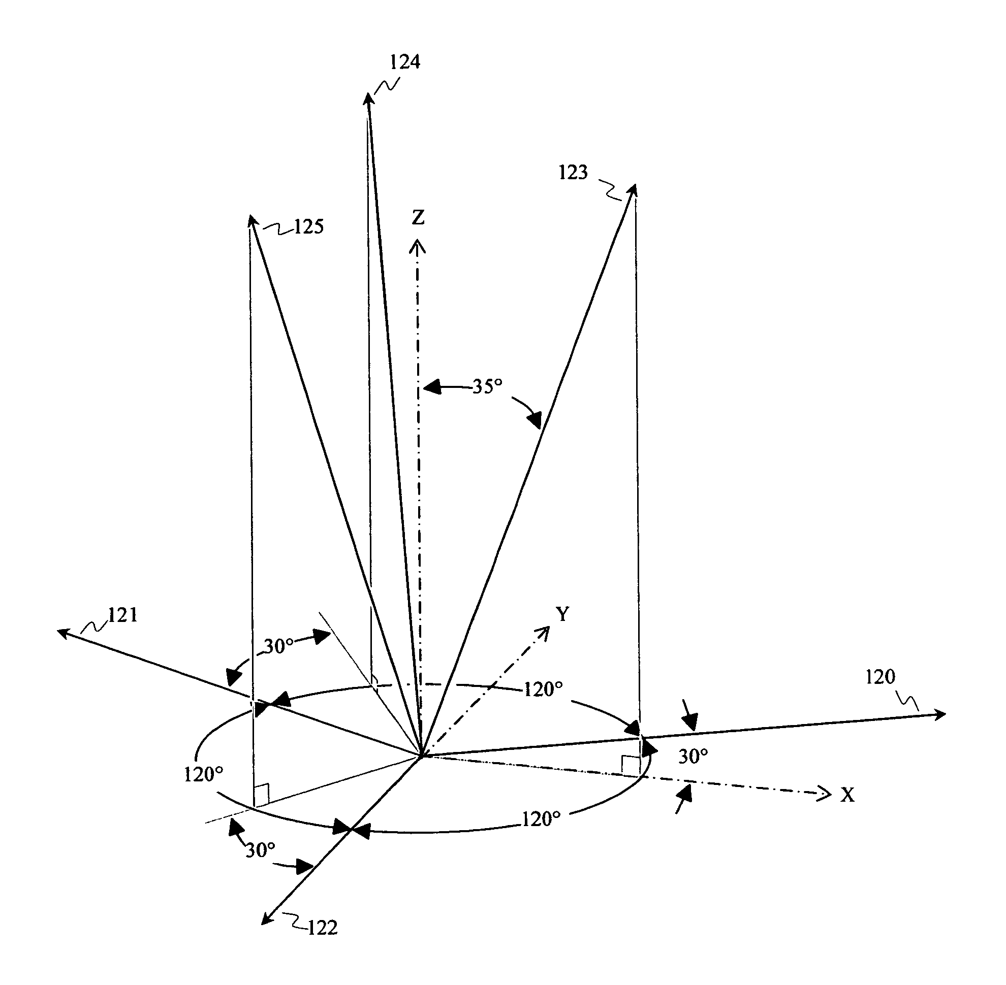
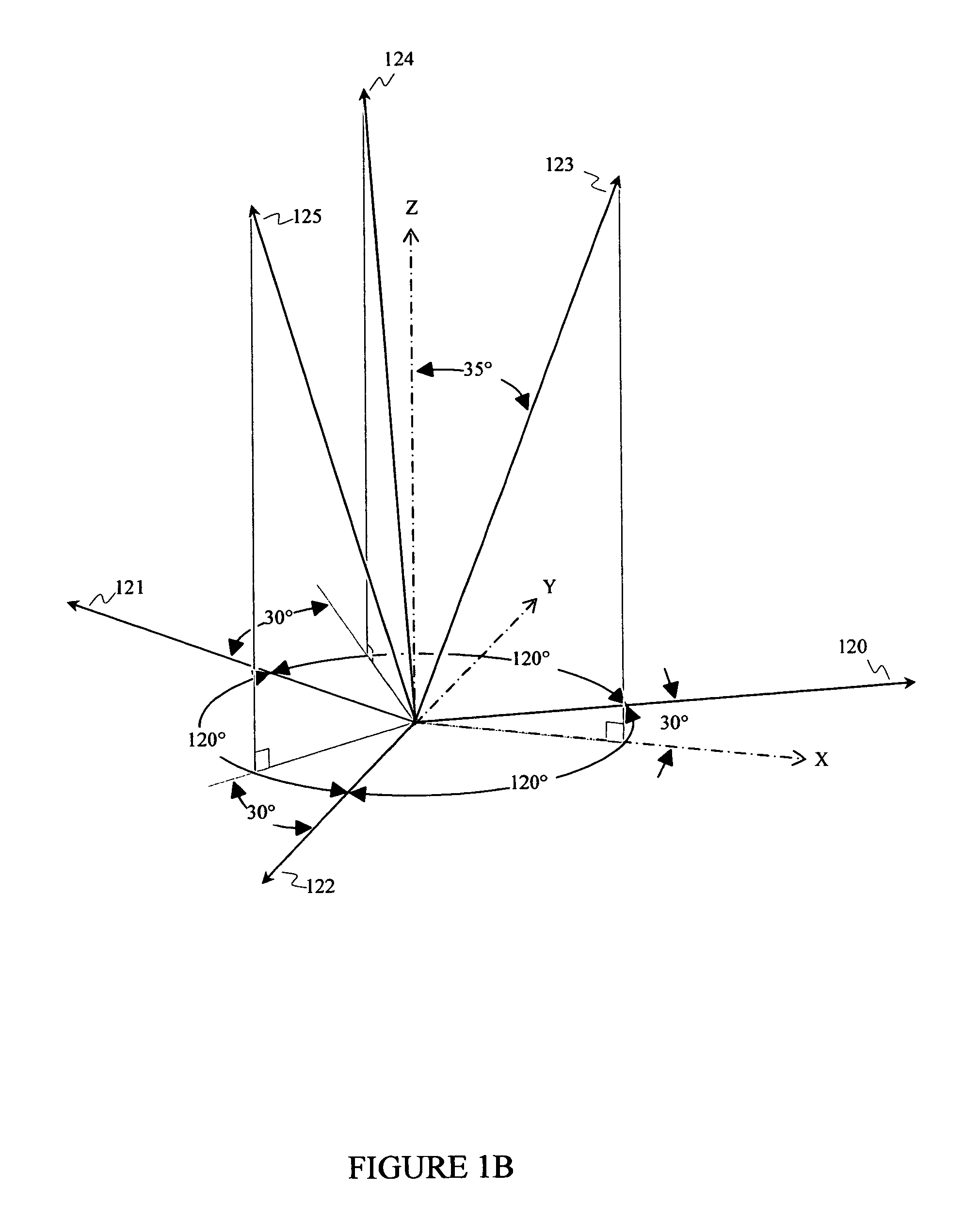
[0022]FIG. 1A is a diagram illustrating a perspective view of self-assembly cell 100. FIG. 1B is a perspective diagram indicating the axes of self-assembly cell 100. Self-assembly cell 100 has six yoke electromagnets 110 through 115 oriented along axes 120 through 125 to apply a magnetic force corresponding to the vector addition of the applied fields. Axes 120 through 125 correspond to the well-known crystallographic axes of an opal structure. The direction of the magnetic field is electrically modulated between electromagnets 110 through 115. Alternatively, a single electromagnet may be used and mechanically rotated to the desired direction. Sample 101 is located at the center of self-assembly cell 100.

[0023]FIG. 2 is a flowchart with diagrams illustrating the side view of an electroplated inverse opal PBG...


PUM

PropertyMeasurementUnit
areaaaaaaaaaaa
sizeaaaaaaaaaa
lattice sizeaaaaaaaaaa

Abstract

A colloidal suspension of particles is rapidly self-assembled with a minimum number of defects into a densely packed array of particles on a substrate under simultaneous sedimentation and annealing forces. The particles may be ordered as an opal structure. Optionally, the synthesized structure may incorporate an electrolyte and be used as a sacrificial form for micromolding an inverse structure. The inverse structure may exhibit a photonic band gap. Optionally, necking between particles may be adjusted after micromolding. Furthermore, a shell may alter physical properties, such as protecting a thermally stimulated photonic band gap device. These low cost methods allow more applications to become commercially viable.

Description

TECHNICAL FIELD OF THE INVENTION[0001]This invention relates generally to the fields of photonics and microfabrication, more specifically to a system and method to fabricate synthetic opal structures, inverse opal structures, and inverse opal photonic band gap crystals.BACKGROUND OF THE INVENTION[0002]A Photonic Crystal (PC) is a microstructured material with wavelength- and angle-dependent optical properties. For a Photonic Band Gap (PBG) to exist within a PC, the allowed quantum energy bands must not overlap for some area, and that gap area is the PBG. The PBG may exist in one, two, or three dimensions and in TE and / or TM modes. A complete 3-D PBG is a gap in the allowed quantum states across all propagation directions and polarization modes. The band gap position and gap width may be easily modified to yield desired photonic properties by varying crystal parameters, such as: structural geometry, crystal lattice dimensions, or contrast of indices of refraction between the composit...

Claims


Application Information

Patent Timeline
Patent Type & Authority Patents(United States)
IPC IPC(8): C30B35/00C30B29/00C30B5/00C30B29/60C30B1/00
CPCC30B5/00C30B29/60Y10T117/10C30B29/00
Inventor MARSHALL, ROBERT, A.
Owner PRACTICAL TECH
Learn More