
Electric rotary machine for motor vehicle

a technology of electric rotary machines and motor vehicles, which is applied in the direction of electric generator control, dynamo-electric converter control, transportation and packaging, etc., can solve the problems of reducing the reliability of the alternator, mos transistors in the bridge circuit and the internal circuit are damaged, and the motor vehicle and various components of the alternator are often damaged, so as to prevent the output voltage from increasing, reduce the increased amount of output voltage, and prevent the effect of supplying a high voltag

Active Publication Date: 2015-01-06
DENSO CORP
View PDF25 Cites 4 Cited by
  • Summary
  • Abstract
  • Description
  • Claims
  • Application Information

AI Technical Summary

Benefits of technology

This design effectively prevents high voltage generation during load dumps, increasing the reliability of the alternator by minimizing power loss and reducing the risk of MOS transistor damage, ensuring prolonged and efficient rectifying operations.

Problems solved by technology

As a result, the electrical loads mounted to the motor vehicle and various components in the alternator are often damaged by generated load dump surges.
As a result, the MOS transistors in the bridge circuit and the internal circuit are damaged by the increased terminal voltage of the alternator.
This decreases the reliability of the alternator.
However, when the capacitor connected to the output terminal of the alternator has a small capacitance, the number of repetitions to repeatedly execute the load dump protection operation and stop the load dump protection operation increases, a power loss is accordingly accumulated.
As a result, there is a possibility of damaging the MOS transistors in the bridge circuit.
In particular, such occurrence of damage extremely increases when the charging wires are disconnected from the output terminals of the alternator.

Method used


Image

  • Electric rotary machine for motor vehicle
  • Electric rotary machine for motor vehicle
  • Electric rotary machine for motor vehicle

Examples


Embodiment Construction

[0023]Hereinafter, various embodiments of the present invention will be described with reference to the accompanying drawings. In the following description of the various embodiments, like reference characters or numerals designate like or equivalent component parts throughout the several diagrams.

Exemplary Embodiment

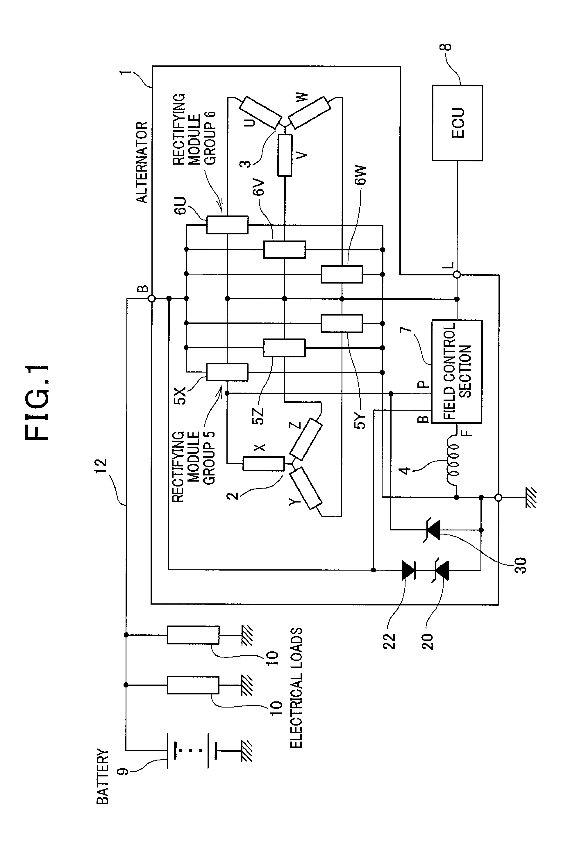
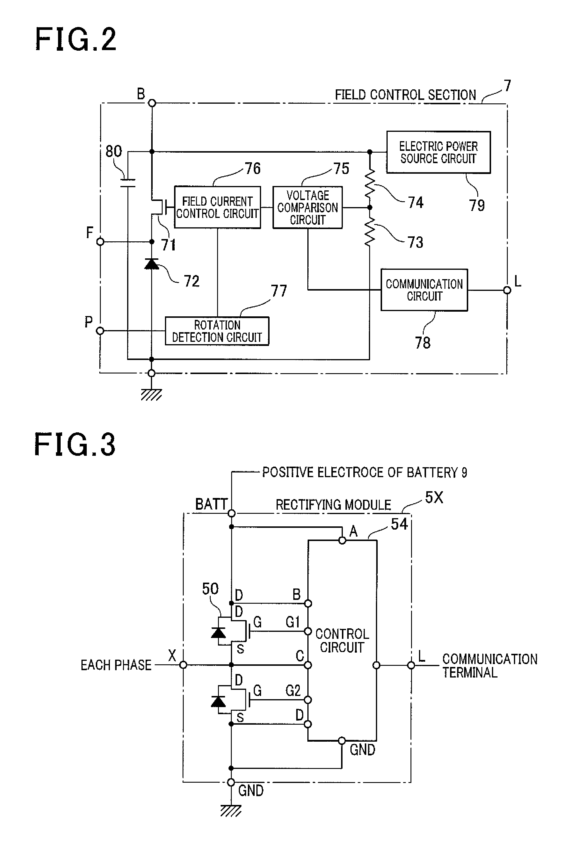
[0024]A description will be given of an alternator 1 as an electric rotary machine to be used in motor vehicles according to an exemplary embodiment with reference to FIG. 1 to FIG. 10.

[0025]FIG. 1 is a view showing a structure of the alternator 1 for motor vehicles according to an exemplary embodiment. As shown in FIG. 1, the alternator 1 is comprised of two stator windings (or armature windings) 2 and 3 and a field winding 4, two rectifying module groups 5 and 6, a field control section 7, Zener diodes 20 and 30, and a diode 22 (as a current limiting element). The Zener diode 20 corresponds to the first Zener diode used in the claims. The diode 22 corresponds to the c...


PUM


Abstract

An alternator has rectifying module groups. The rectifying module groups form a bridge circuit. The rectifying module groups have a load dump protection judgment section for monitoring an output voltage of rectifying module groups. When the monitored output voltage exceeds a first threshold voltage, the load dump protection judgment section provides to a control section an instruction to turn on MOS transistors in a lower arm of the bridge circuit at a time when a predetermined delay time has elapsed. When a second threshold voltage is lower than the first threshold voltage and the monitored output voltage becomes less than the second threshold voltage after the monitored output voltage exceeds the first threshold voltage, the load dump protection judgment section provides to the control circuit an instruction to turn on the MOS transistors in the lower arm after the MOS transistors are turned off during a predetermined time length.

Description

CROSS-REFERENCE TO RELATED APPLICATION[0001]This application is related to and claims priority from Japanese Patent Application No. 2012-178028 filed on Aug. 10, 2012, the contents of which are hereby incorporated by reference.BACKGROUND OF THE INVENTION[0002]1. Field of the Invention[0003]The present invention relates to electric rotary machines or alternators to be mounted to motor vehicles such as passenger vehicles and trucks.[0004]2. Description of the Related Art[0005]An alternator mounted to a motor vehicle generates electric power by a driving force transmitted from an internal combustion engine of the motor vehicle. Output terminals of the alternator are connected to terminals of a battery mounted to the motor vehicle through charging wires. The alternator supplies the generated electric power to the battery through the charging wires. The alternator further supplies the generated electric power to various electrical loads mounted to the motor vehicle through other wires. W...

Claims


Application Information

Patent Timeline
Patent Type & Authority Patents(United States)
IPC IPC(8): H02P11/00H02J7/14H02J7/16H02P9/04
CPCH02P9/107H02P9/48H02P9/102
Inventor MARUYAMA, TOSHINORINAKANISHI, MASAYAKIMURA, ASAKAINOKUCHI, TAKATOSHI
Owner DENSO CORP
Learn More