
Electric machine having a hybrid-excited rotor

a hybrid-excited rotor and electric machine technology, applied in the field of electric machines, can solve the problems of occupying a lot of space on the rotor, requiring plenty of space, and complicating the magnetization of the rotor, so as to reduce the amount of copper, the space needed, and the overall required cross section.

Active Publication Date: 2014-12-30
SEG AUTOMOTIVE GERMANY GMBH
View PDF38 Cites 8 Cited by
  • Summary
  • Abstract
  • Description
  • Claims
  • Application Information

AI Technical Summary

Benefits of technology

This patent is about an electric machine that can operate as a generator. It is designed to reduce the energy lost during operation without needing extra parts. This is achieved by using a special rotor design with fewer coils and a more compact size. The machine also has a stator winding that matches the number of poles in the rotor, which improves efficiency and reduces ripple in the output voltage. Overall, this design results in a more compact, cost-effective, and efficient electric machine.

Problems solved by technology

The disadvantage here is that, for a symmetrical pole arrangement, one field coil for an appropriate magnetomotive force is needed for each permanent magnet.
This requires a correspondingly large copper cross section and takes up plenty of space on the rotor.
It is also disadvantageous that the permanent magnets on the rotor circumference have the same polarity which complicates their magnetization in the installed state since the magnetic reflux must take place via adjacent poles.
For a machine having a twelve-pole rotor, even four field coils having a correspondingly large copper cross section are needed and require plenty of space.
It is disadvantageous here also that complete magnetization of the permanent magnets in the installed state on the rotor is almost impossible because the interior areas of the permanent magnets are not reached to the full extent by a magnetizing head on the rotor circumference.

Method used


Image

  • Electric machine having a hybrid-excited rotor
  • Electric machine having a hybrid-excited rotor
  • Electric machine having a hybrid-excited rotor

Examples


Embodiment Construction

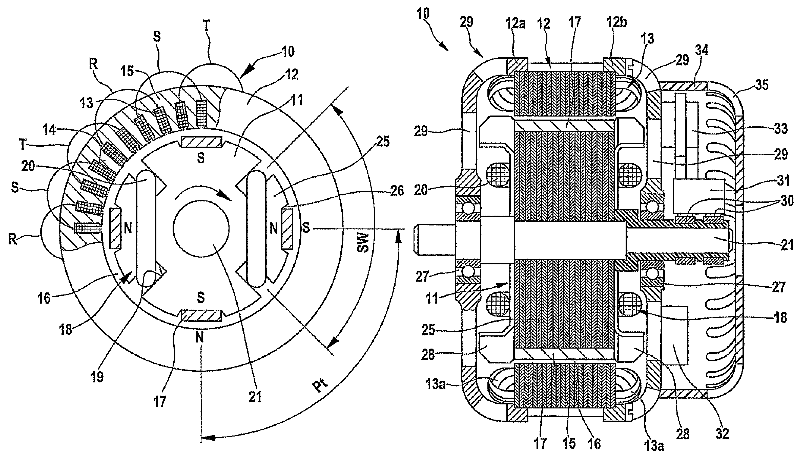
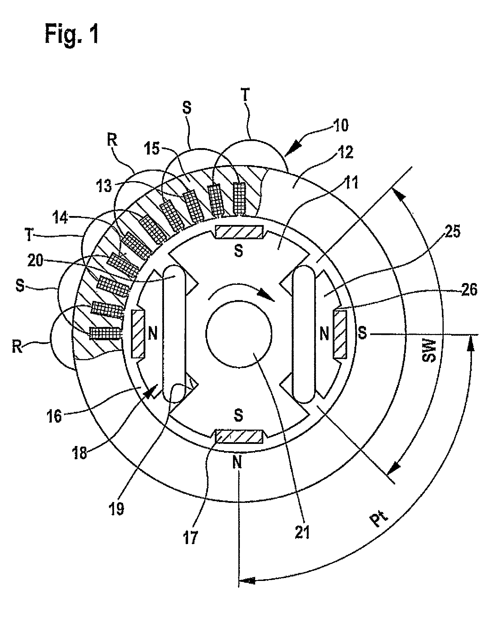
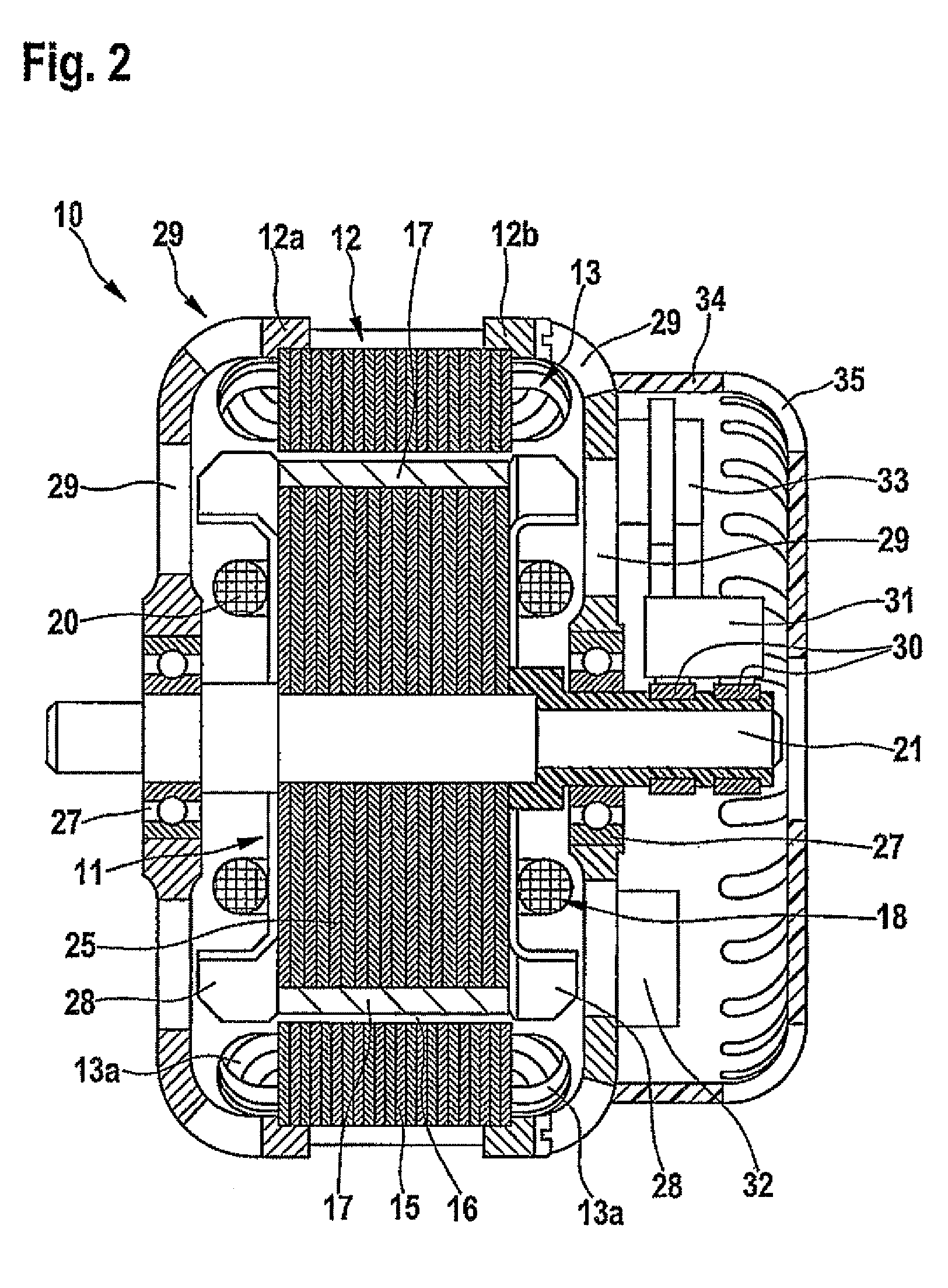
[0025]FIGS. 1 and 2 show an electric machine in simplified form in cross section and longitudinal section, and labeled with reference numeral 10 which, as a synchronous machine, is equipped with a hybrid-excited rotor 11. The machine has a fixed stator 12 which carries a three-phase stator winding 13. In the first exemplary embodiment according to FIGS. 1 through 3, electric machine 10 is a three-phase generator for motor vehicles having a twelve-pole stator winding 13 whose three phase windings R, S, and T are inserted into grooves 14 of a laminated stator core 15 having a coil step size of three grooves and are shown in FIG. 1 across part of the circumference. Stator 12 cooperates, via an operating air gap 16, with rotor 11 which is rotatably supported in stator 12. Rotor 11 has multiple north poles and south poles N and S in a predefined sequence over its circumference, which are formed by permanent magnets 17 and by field coils 18. The number of poles of rotor 11 may be changed ...


PUM


Abstract

A synchronous electric machine having a fixed stator, a multi-phase stator winding and having a rotor which has poles, excited in a predefined sequence, over its circumference, the number of poles being changeable as a function of the intensity and the direction of a field current in at least one field coil of the rotor. For improving the efficiency of the machine and for reducing the number of field coils and the entire coil cross section it is provided that the rotor has a laminated core, laminated in the axial direction, which has grooves on the circumference for accommodating the at least one field coil and that the at least one field coil is situated on the circumference of the rotor with a step size which corresponds to the pole pitch of the lower number of poles.

Description

FIELD OF THE INVENTION[0001]The present invention relates to an electric machine having a fixed stator and a hybrid-excited rotor.BACKGROUND INFORMATION[0002]Synchronous machines of this type are suitable for operation on a fixed power system, e.g., a fixed three-phase system, as well as for operation via an electronic converter. Moreover, machines of this type are suitable in generator operation for regulating the induced voltage in a multi-phase stator winding system as they are needed in electrical systems of motor vehicles, for example. In these electric machines, the poles on the circumference of the rotor are excited partly by permanent magnets and partly electrically.[0003]Pole-changing synchronous machines are discussed in WO 2004 / 017496 in which pole-changing of the rotor takes place by changing the direction of the current in the field coils of the rotor, this change being used for controlling the output voltage of a multi-phase stator winding. By continuously regulating t...

Claims


Application Information

Patent Timeline
Patent Type & Authority Patents(United States)
IPC IPC(8): H02K21/04
CPCH02K21/042
Inventor REUTLINGER, KURT
Owner SEG AUTOMOTIVE GERMANY GMBH
Learn More