
Protection of chips against attacks

a chip and chip technology, applied in the field of chips, can solve the problems of preventing a potential attacker from performing current analysis, unable to use elements, and failure of the protection mechanism, so as to prevent the use of chip cards and facilitate the tracking of chip cards

Inactive Publication Date: 2014-12-23
INFINEON TECH AG
View PDF27 Cites 0 Cited by
  • Summary
  • Abstract
  • Description
  • Claims
  • Application Information

AI Technical Summary

Benefits of technology

The present invention provides a chip with a time reference and clock number reference, which allows a processing means or external device to prevent a predetermined operation when a certain time and number of counts, respectively, is exceeded. This prevents unauthorized access to the chip and ensures secure operations. Additionally, the chip can store information about the duration of potential attacks and signal these to an external device, which enables, for example, prevention of the usage of chip cards beyond a certain operating time. The chip can also track the manipulation of chip cards, making it easier to identify the person responsible for the manipulation.

Problems solved by technology

However, this method does not prevent a potential attacker from performing current analysis, spike attacks and similar attacks to the chip across an unlimited time or across an unlimited number of clock cycles.
For these attacks, an authentification is not required, which is why the protection mechanism fails.
The problem with trying to prevent further attacks, which require no authentification, is that current chip testers with microcontrollers and security memories such as a smart card, have no clock, so that the operation cannot be limited in time.
Due to their thickness, these elements cannot be used in the chip cards widely spread today.

Method used


Image

  • Protection of chips against attacks
  • Protection of chips against attacks
  • Protection of chips against attacks

Examples


Embodiment Construction

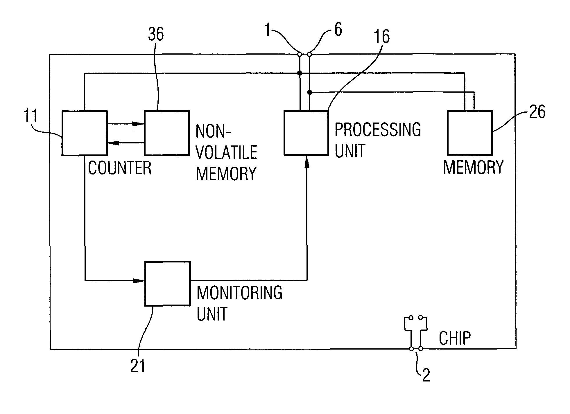
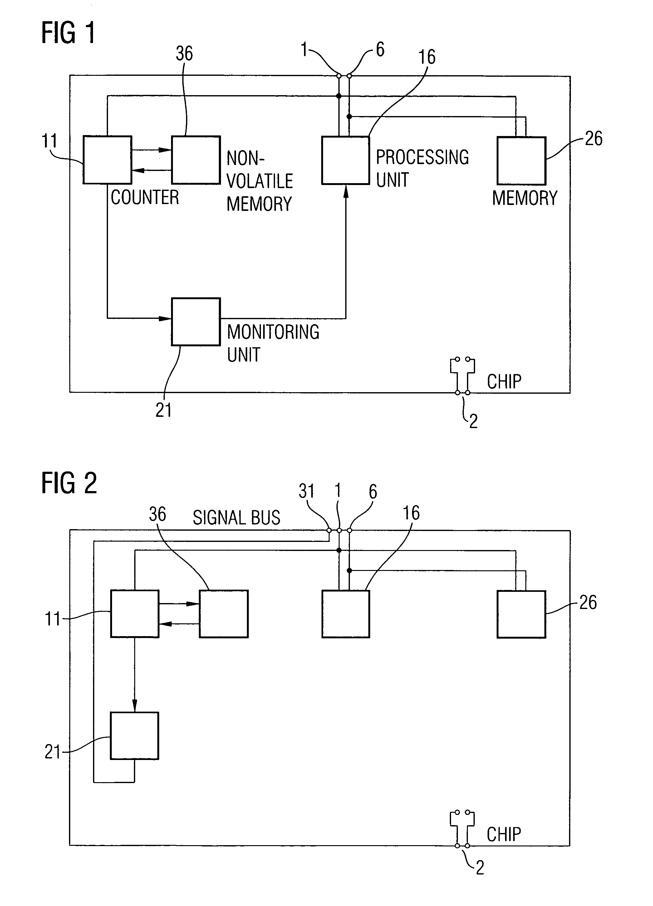
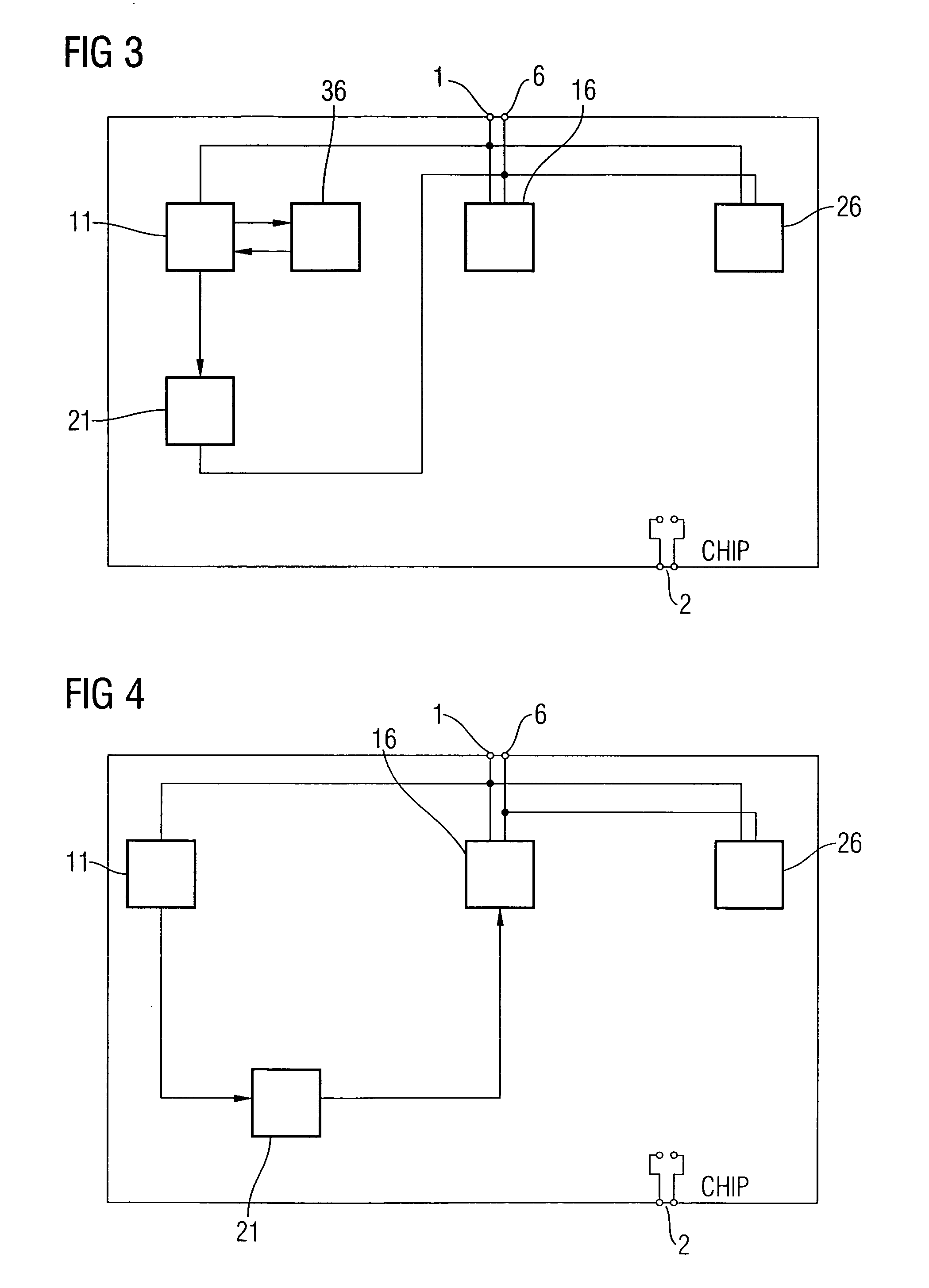
[0027]FIG. 1 shows a block diagram of a chip according to an embodiment of the present invention. The block diagram comprises a clock terminal 1, a supply voltage terminal 2, a data bus terminal 6, a counter 11, a non-volatile memory 36, a processing unit 16, a memory 26 and a monitor unit 21. The clock terminal 1 is connected to an input of the counter 11, an input of the processing unit 16 and an input of the memory 26.

[0028]The data terminal 6 is connected to the processing unit 16 or the memory 26, wherein the connection can be made via a processing data bus, which is either in the form of a line or in the form of several lines. These lines can then be divided into lines for addresses and / or data and / or chip select and / or instruction signals, for example. The data bus terminal 6 is connected to the processing unit 16 and to the memory 26. An output of the counter 11 is connected to an input of the non-volatile memory 36, while an output of the non-volatile memory 36 is connected...


PUM


Abstract

A chip including a processor for performing a predetermined operation, a provider for providing a clock signal, with which the processor is clocked, a counter for decrementing or incrementing a count based on the clock signal, a monitor for signaling the predetermined operation to be prevented, depending on the count, and a non-volatile storage for non-volatily storing the count.

Description

CROSS-REFERENCE TO RELATED APPLICATION[0001]This application claims priority from German Patent Application No. 10360998.9, which was filed on Dec. 23, 2003 and is incorporated herein by reference in its entirety.BACKGROUND OF THE INVENTION[0002]1. Field of the Invention[0003]The present invention relates to chips, and more particularly to protection of chips to prevent unlimited access to the same.[0004]2. Description of the Related Art[0005]The protection concepts of current chips are designed such that they determine only the number of authentification attempts and authentifications, respectively. In the present application, chips mean a semiconductor apparatus with integrated circuitry, while chip cards consist of the chip and a carrier, such as a plastic carrier. In a current GSM SIM card, for example, the number of potential authentification attempts is limited to three. A program in a processing unit in a GSM SIM card determines the number of authentification attempts via a c...

Claims


Application Information

Patent Timeline
Patent Type & Authority Patents(United States)
IPC IPC(8): G06Q20/34G06F21/00G06F12/00G06K19/073G07F7/08G07F7/10
CPCG07F7/082G07F7/1008G06Q20/341
Inventor LAACKMANN, PETER
Owner INFINEON TECH AG
Learn More