Gradient-index (GRIN) lens fabrication employing laser pulse width duration control, and related components, systems, and methods
a technology of laser pulse width duration control and gradient index, which is applied in the field of fabrication of gradient index (grin) lenses, can solve the problems of introducing optical losses, damage or cracking of grin lenses, and labor-intensive mechanical polishing processes, so as to prevent or reduce heat accumulation in grin rods, and facilitate efficient light collimation
- Summary
- Abstract
- Description
- Claims
- Application Information
AI Technical Summary
Benefits of technology
Problems solved by technology
Method used
Image

Examples
Embodiment Construction
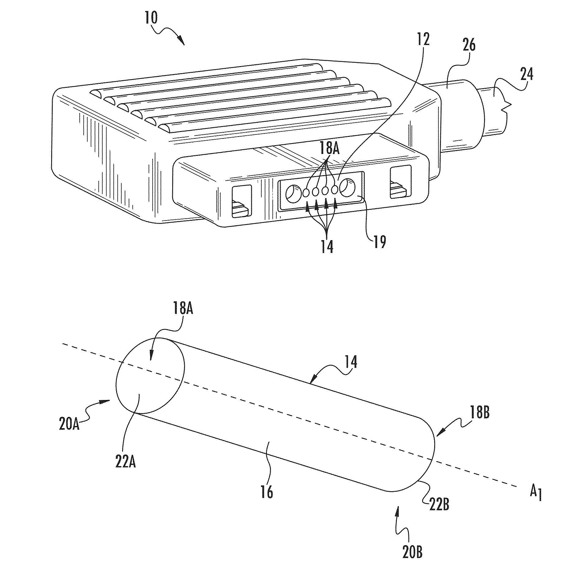
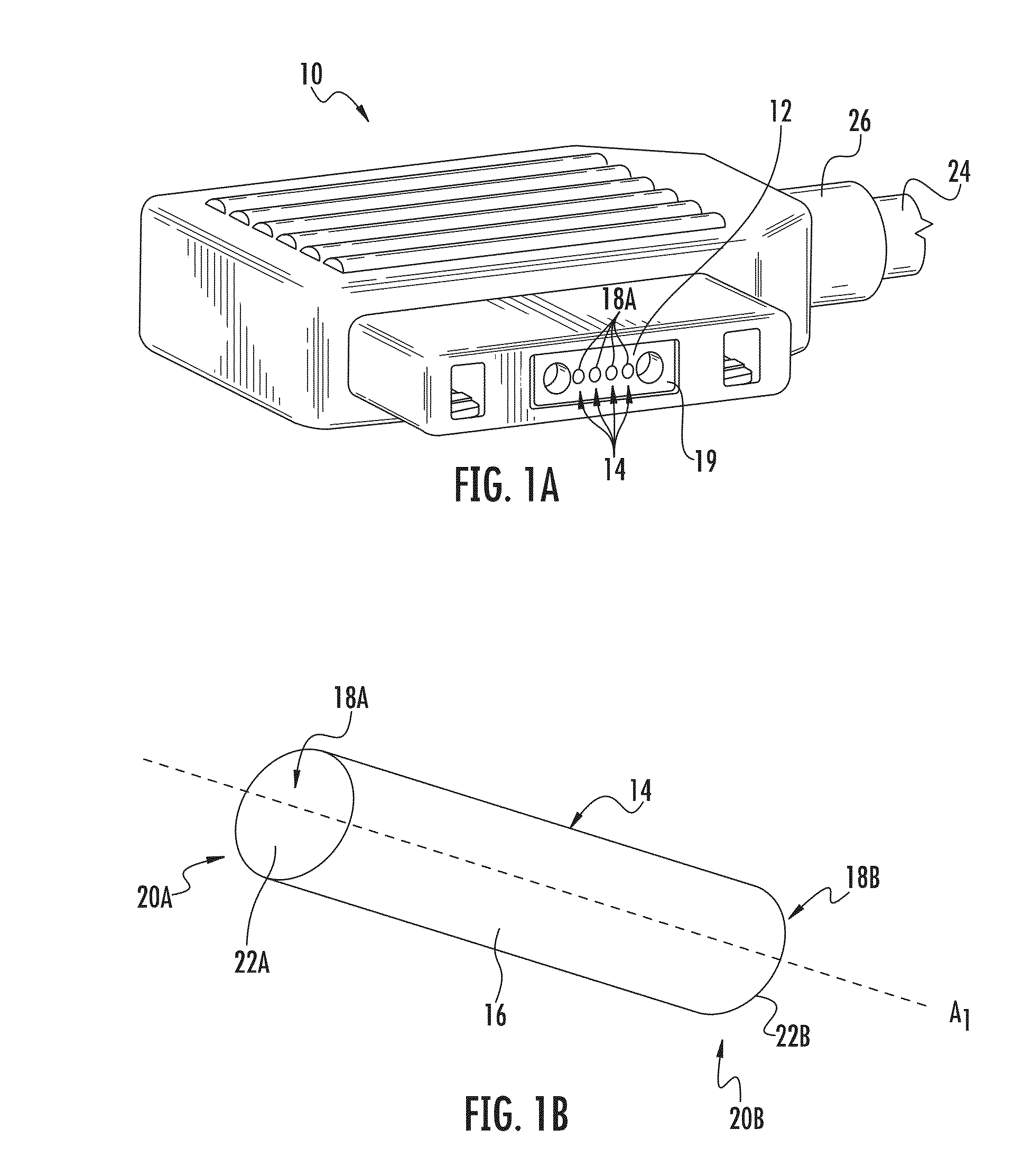
[0009]Embodiments disclosed herein include gradient-index (GRIN) lens fabrication employing laser pulse width duration control, and related components, systems, and methods. GRIN lenses can be fabricated from GRIN rods by laser cutting and related processes. The fabricated GRIN lenses may be employed in a fiber optic connector and / or other fiber optic components for facilitating optical connections, including for high bandwidth communications rates.
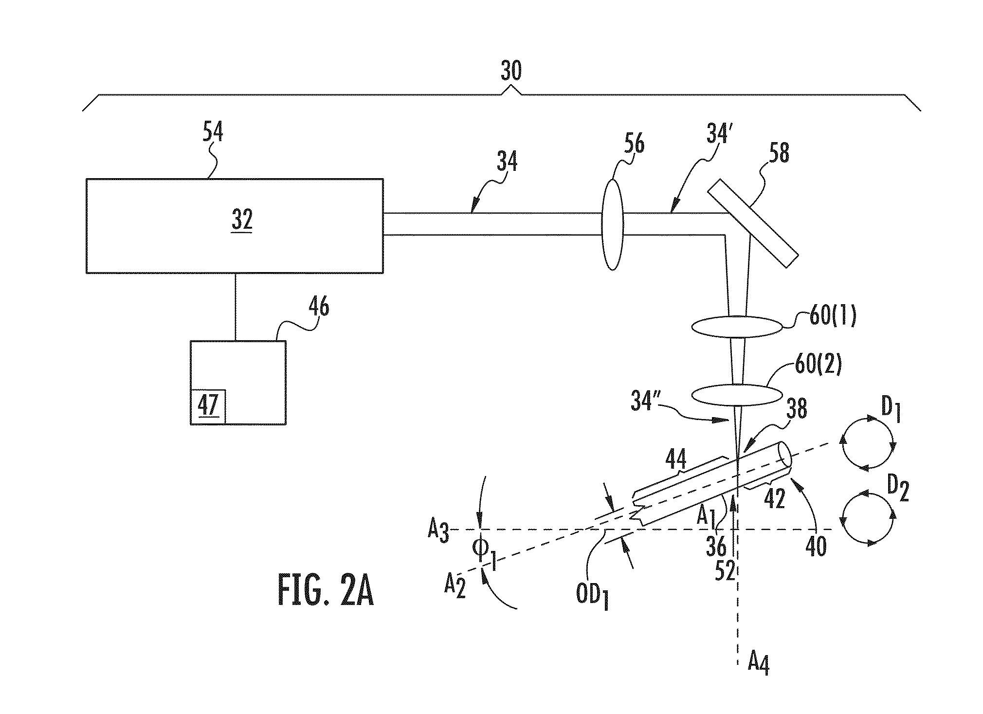
[0010]In this regard, GRIN lenses can be fabricated from GRIN rods by controlling the pulse width emission duration of a laser beam emitted by a laser to laser cut the GRIN rod, as the GRIN rod is disposed in rotational relation to the laser beam. Controlling laser pulse width emission duration to fabricate GRIN lenses can prevent or reduce heat accumulation in the GRIN rod during GRIN lens fabrication. Heat accumulation can lead to rounding of end face optical surfaces fabricated in a GRIN lens. It is desired that the end faces of GRIN l...
PUM
| Property | Measurement | Unit |
|---|---|---|
| outer diameter | aaaaa | aaaaa |
| power | aaaaa | aaaaa |
| temperatures | aaaaa | aaaaa |
Abstract
Description
Claims
Application Information
 - R&D
- Intellectual Property
- Life Sciences
- Materials
- Tech Scout
- Unparalleled Data Quality
- Higher Quality Content
- 60% Fewer Hallucinations
Browse by: Latest US Patents, China's latest patents, Technical Efficacy Thesaurus, Application Domain, Technology Topic, Popular Technical Reports.
© 2025 PatSnap. All rights reserved.Legal|Privacy policy|Modern Slavery Act Transparency Statement|Sitemap|About US| Contact US: help@patsnap.com