
Receptacle contact

a technology of receptacles and contacts, applied in the field of receptacle contacts, can solve the problems of reducing the reliability of electrical connections, and reducing the reliability of connectors, so as to achieve stable and reliable electrical connections

Active Publication Date: 2014-12-16
TYCO ELECTRONICS LOGISTICS AG (CH)
View PDF13 Cites 9 Cited by
  • Summary
  • Abstract
  • Description
  • Claims
  • Application Information

AI Technical Summary

Benefits of technology

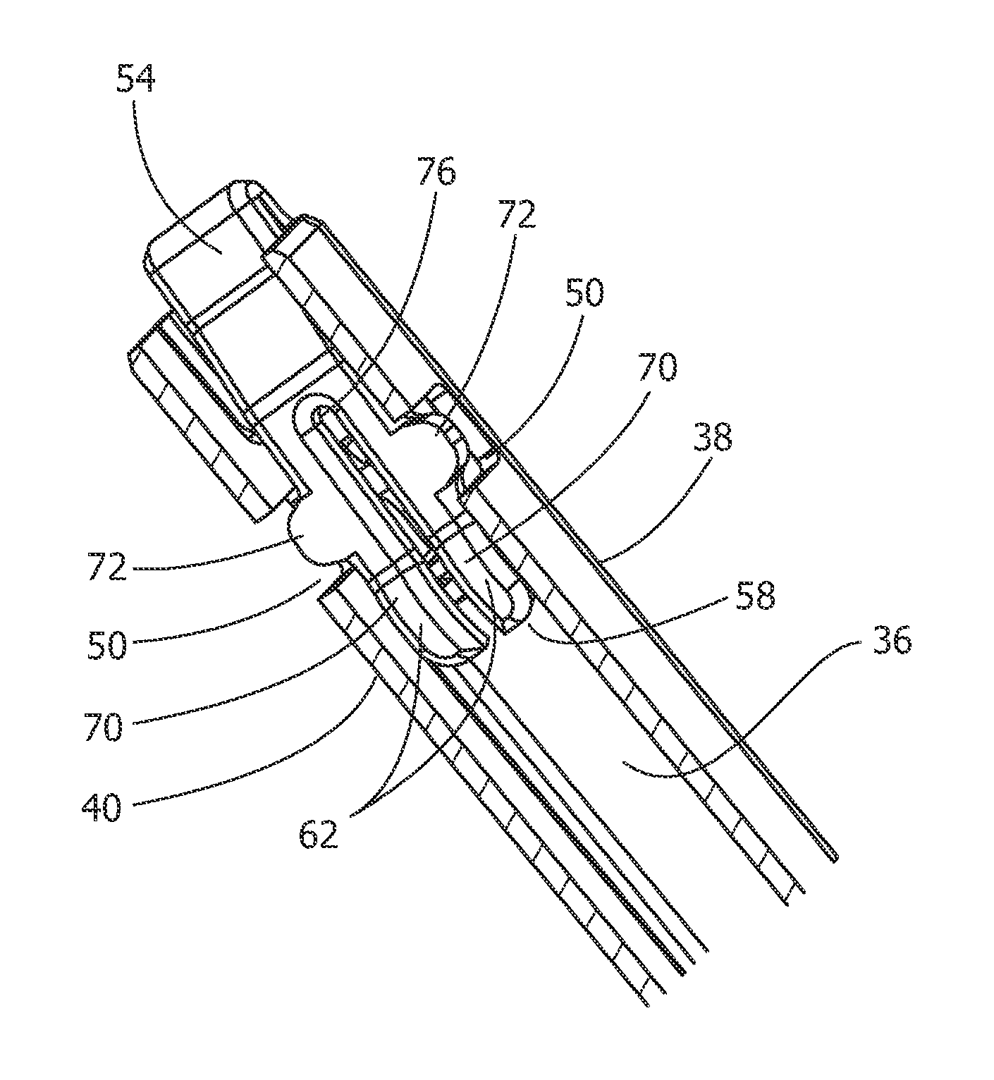
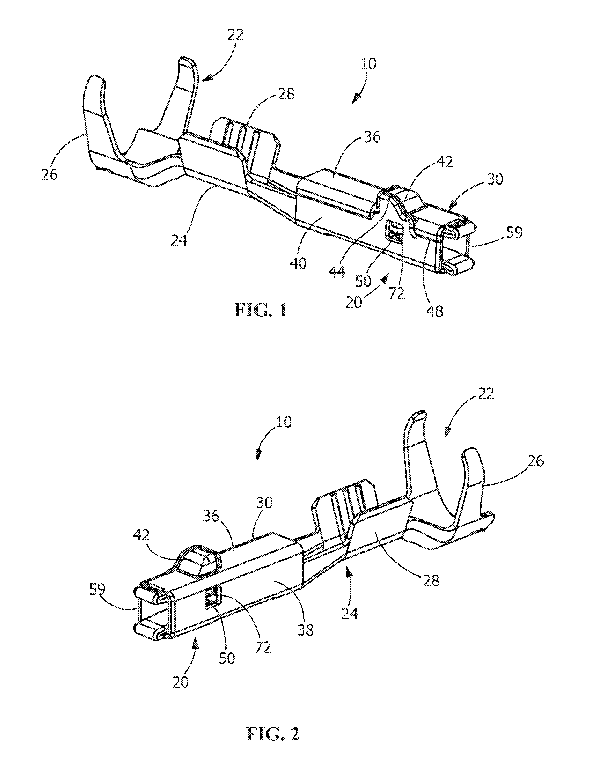
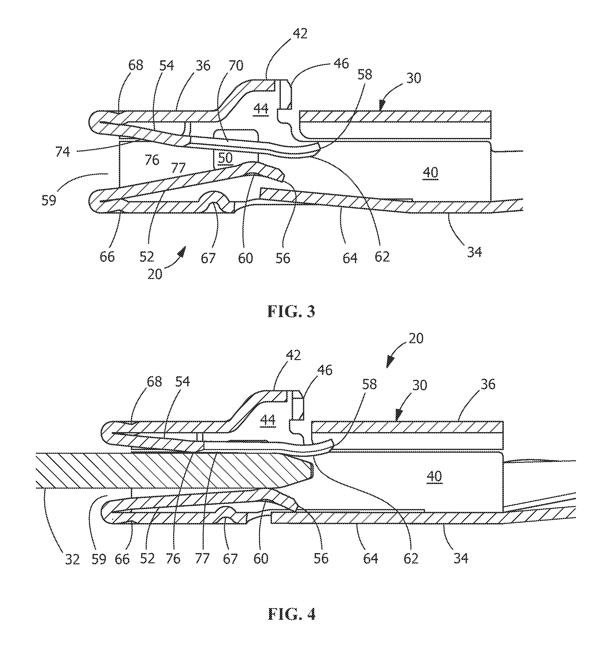
[0008]An exemplary embodiment is directed to a receptacle contact for receipt of a mating contact therein. The receptacle contact has side walls, each of the side walls has an opening provide therein. A first resilient contact arm extends between the side walls. The first resilient contact arm has a fixed end and a free end with at least one first contact area positioned proximate to the free end. Projections extend from the first resilient contact arm, the projections extend through the openings of the side walls. A weak area is provided on the first resilient contact arm, the weak area positioned between the fixed end of the first resilient contact arm and the projections of the first resilient contact arm. The weak area having a second contact area positioned proximate thereto. A second resilient contact arm extends between the side walls. The second resilient contact arm has a fixed end and a free end. A third contact area is positioned proximate to the free end of the second resilient contact arm. The third contact area is positioned laterally between the at least one first contact area of the first resilient contact arm and the weak area of the first resilient contact arm. The projections engage a wall of the opening as the mating contact is inserted into the receptacle contact, causing the second contact area proximate the weak area to move into engagement with the mating contact, thereby providing multiple areas of contact between the first and second resilient contact arms and the mating contact to provide a stable and reliable electrical connection therebetween.
[0009]An exemplary method is directed to a method of inserting a mating contact into a receptacle contact, the receptacle contact having side walls and at least one resilient contact arm, the method comprising: engaging the at least one resilient contact arm with the mating contact; moving the at least one resilient contact arm from an unstressed position; engaging a wall of an opening with at least one projection of the at least one resilient contact arm to prevent further movement of a weak area of the at least one resilient contact arm; and moving a portion of the at least one resilient contact arm about the weak area of the at least one resilient contact arm after the at least one projection has engaged the wall of the opening.

Problems solved by technology

This can result in a lack of sufficient physical contact that reduces the reliability of the electrical connection and renders the connector susceptible to reduction or loss of connection.
Further, vibration or other motion or movement may result in a loss of connection.
In addition, some known connectors have contact beams that have a high spring force, which decreases the ability to control the normal force applied by the contact beam, increasing the mating force of the connector, and increasing tolerance sensitivity.
Other connector problems may arise from having the contact beam exposed to the mating pin, leaving the contact beam unprotected from damage from external factors.

Method used


Image

  • Receptacle contact
  • Receptacle contact
  • Receptacle contact

Examples


Embodiment Construction

[0019]In the following detailed description, numerous specific details are set forth in order to provide a thorough understanding of various embodiments. However, those skilled in the art will understand that the embodiments may be practiced without these specific details, that the embodiments are not limited to the depicted embodiments, and that the embodiments may be practiced in a variety of alternative embodiments. In other instances, well known methods, procedures, and components have not been described in detail.

[0020]Further, various operations may be described as multiple discrete steps performed in a manner that is helpful for understanding the embodiments. However, the order of description should not be construed as to imply that these operations need be performed in the order they are presented, or that they are even order-dependent. Moreover, repeated usage of the phrase “in an embodiment” does not necessarily refer to the same embodiment, although it may. Lastly, the te...


PUM

PropertyMeasurementUnit
angleaaaaaaaaaa
contact areaaaaaaaaaaa
areaaaaaaaaaaa

Abstract

A receptacle contact for receipt of a mating contact and a method therefore. The receptacle contact has side walls, each of the side walls has an opening provide therein. A resilient contact arm extends between the side walls. Projections extend from the resilient contact arm and extend through the openings of the side walls. A weak area is provided on the resilient contact arm, the weak area positioned between the fixed end and the projections. The projections engage a wall of the opening as the mating contact is inserted into the receptacle contact, causing the at least one contact area to become fixed and allowing the weak area to move into engagement with the mating contact, thereby providing multiple areas of contact between the resilient contact arm and the mating contact.

Description

CROSS-REFERENCES TO RELATED APPLICATIONS[0001]This application claims the priority of U.S. provisional patent application No. 61 / 496,086 filed Jun. 13, 2011, incorporated herein by reference in its entirety.FIELD OF THE INVENTION[0002]The invention relates to receptacle contacts, and more particularly to receptacle contacts with multiple contact areas.BACKGROUND OF THE INVENTION[0003]Currently electrical contacts or wire contacts are used to terminate a wire. Wire contacts require a strong mechanical means of attaching to the wire to create a permanent termination and a means to mate to a mating contact to form an electrical connection. For example, a wire contact may have a crimp end for terminating the wire and a male or female mating end for a mating contact. Some contacts have been developed from metal strips or pre-plated metal strips, which are stamped and then folded or formed into the appropriate shape. These contacts have a generally box shaped mating end for mating to a co...

Claims


Application Information

Patent Timeline
Patent Type & Authority Patents(United States)
IPC IPC(8): H01R43/16H01R13/11H01R4/48H01R13/187
CPCH01R43/16H01R13/113H01R13/187H01R4/4809Y10T29/49117H01R13/115
Inventor MYER, JOHN MARKMOLL, HURLEY CHESTERKINSEY, JR., FORREST IRVING
Owner TYCO ELECTRONICS LOGISTICS AG (CH)
Learn More