
Rotatable plug and power supply device having the rotatable plug

a technology of rotating plugs and power supply devices, applied in the direction of live contact access prevention, coupling device connections, electrical equipment, etc., can solve the problems of bending and even breaking, and the difficulty of storing conventional power supply devices, and achieve good conduction

Active Publication Date: 2013-09-12
LITE ON TECH CORP +1
View PDF0 Cites 1 Cited by
  • Summary
  • Abstract
  • Description
  • Claims
  • Application Information

AI Technical Summary

Benefits of technology

The present invention provides a rotatable plug that can provide a stable and reliable electrical connection. The conductive terminals are insert molded into the first casing part, ensuring stable and reliable electrical connection. The fixing method is stable and the electrical connection process is reliable. The invention also allows for modularization by cooperating with positioning grooves and connecting the first and second casing parts. Additionally, each arcuate conductive protrusion has at least two points of contact with the depressed contact surface of the corresponding conductive section, enhancing the effect of conduction.

Problems solved by technology

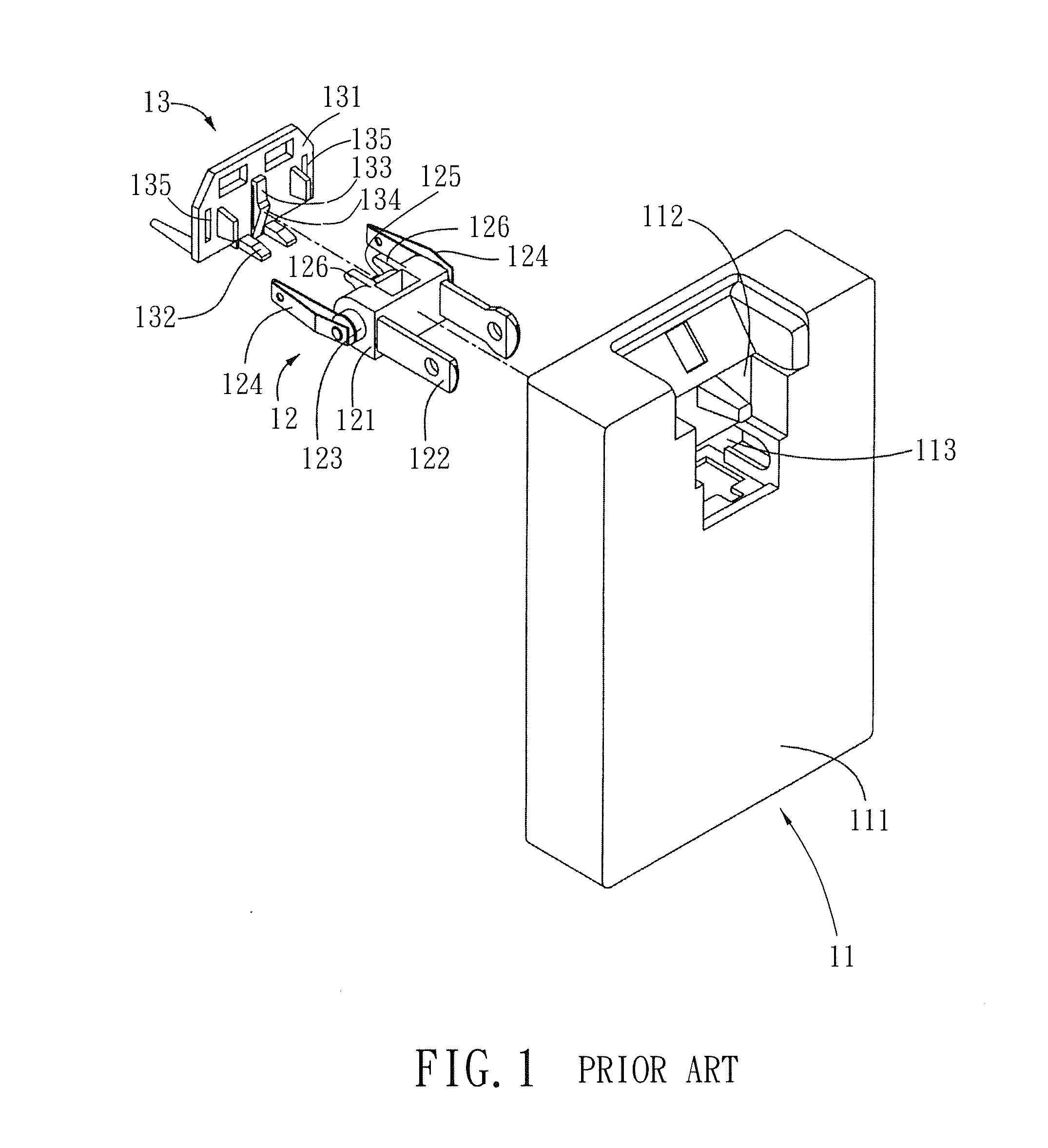
When the power supply device is not in use, because the conductive terminals protrude from the plug body, they are likely to be hit by an external force that may result in the bending and even breakage thereof.
Further, it is difficult to store the conventional power supply device.
However, the above-mentioned device is not modular so that a new mold must be opened in respond to different sizes of housing 11.

Method used


Image

  • Rotatable plug and power supply device having the rotatable plug
  • Rotatable plug and power supply device having the rotatable plug
  • Rotatable plug and power supply device having the rotatable plug

Examples


Embodiment Construction

[0048]The above-mentioned and other technical contents, features, and effects of this invention will be clearly presented from the following detailed description of a preferred embodiment in coordination with the reference drawings.

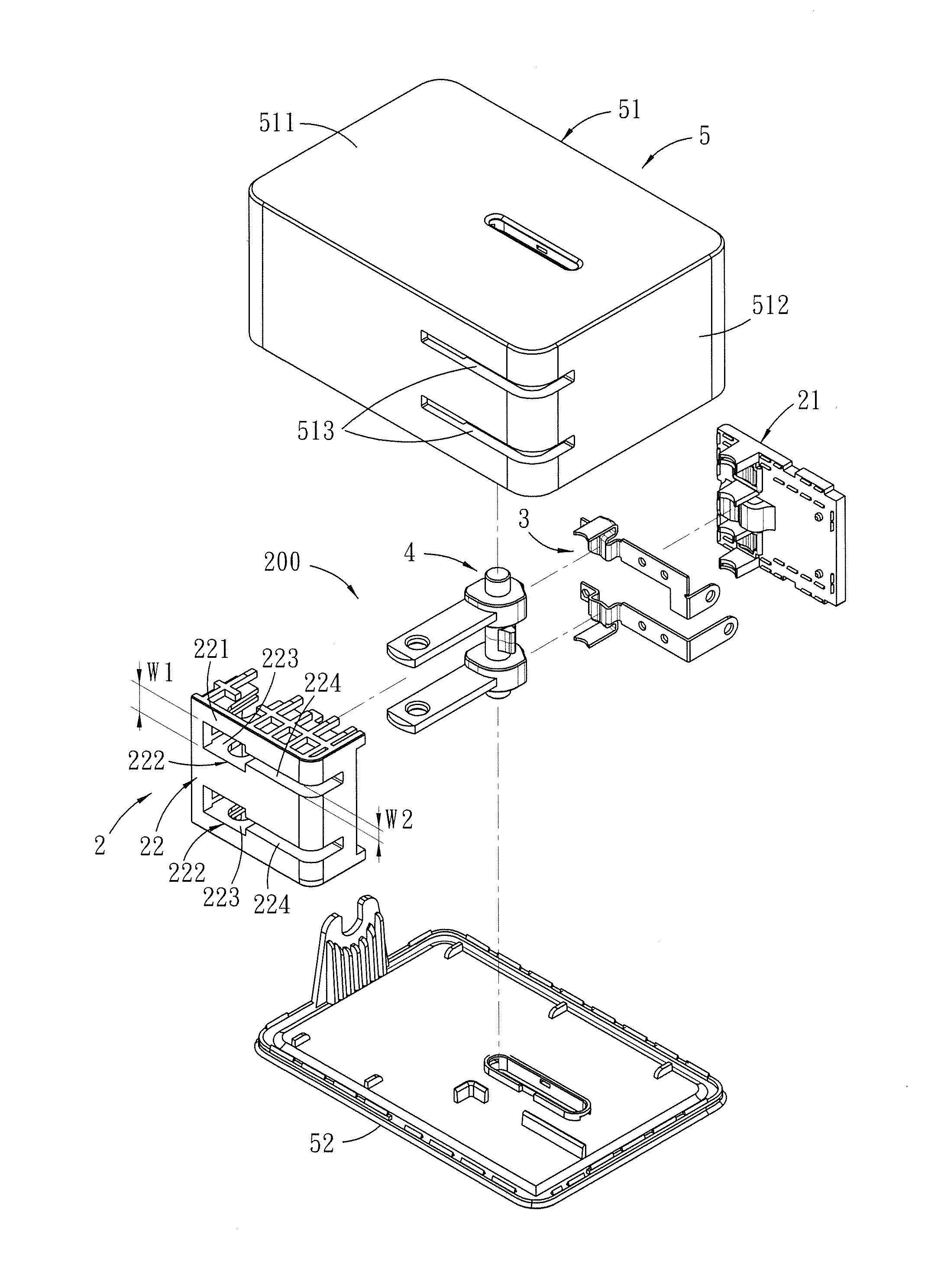
[0049]Referring to FIGS. 4 to 20, a power supply device according to the preferred embodiment of the present invention comprises a housing unit 5, a circuit unit, and a rotatable plug 200.

[0050]The housing unit 5 includes a first housing element 51 and a second housing element 52 connected to and cooperating with the first housing element 51 to define a chamber 53 (see FIG. 18). The first housing element 51 has a base wall 511, a surrounding wall 512 extending transversely from the base wall 511, and two parallel slots 513 formed in the surrounding wall 512.

[0051]As shown in FIGS. 18 and 19, the circuit unit 6 and the rotatable plug 200 are disposed in the chamber 53.

[0052]With reference to FIGS. 4 and 5, the rotatable plug 200 includes a casing unit 2, a...


PUM


Abstract

A rotatable plug includes a casing unit having a first casing part and a second casing part with a pair of receiving spaces, a pair of conductive terminals respectively having conductive sections, and a rotatable unit including a pivot shaft, a pair of conductive prongs connected transversely to the pivot shaft, and a pair of conductive protrusions protruding out from the pivot shaft. The rotatable unit is rotatable relative to the casing unit between non-use and use positions, where the conductive prongs are accommodated in and extend out of the receiving spaces, respectively. Each conductive protrusion has at least two points of contact with the conductive section of a respective conductive terminal.

Description

CROSS-REFERENCE TO RELATED APPLICATION[0001]This application claims priority to Chinese Patent Application No. 201220083223.5, filed on Mar. 7, 2012.BACKGROUND OF THE INVENTION[0002]1. Field of the Invention[0003]The invention relates to a rotatable plug, more particularly to a rotatable plug that can be stored conveniently when not in use and a power supply device having the rotatable plug.[0004]2. Description of the Related Art[0005]A plug of a conventional power supply device includes a plug body and two conductive terminals protruding outwardly from the plug body. When the power supply device is not in use, because the conductive terminals protrude from the plug body, they are likely to be hit by an external force that may result in the bending and even breakage thereof. Further, it is difficult to store the conventional power supply device. Therefore, devices with rotatable plugs have been currently developed to resolve the aforesaid issues.[0006]Referring to FIGS. 1, 2 and 3, ...

Claims


Application Information

Patent Timeline
IPC IPC(8): H01R13/44
CPCH01R31/065H01R13/71
Inventor HSU, CHIA-TSANGCHU, CHIEN-HUA
Owner LITE ON TECH CORP
Learn More