
Cylindrical battery cell adopting non-welding conductive connection and preparation method thereof

A conductive connection, non-welding technology, applied in the field of cylindrical cells and their preparation, can solve the problems of limited space for welding area, poor welding head, long welding time affecting takt time, etc., to reduce equipment procurement and maintenance costs, The effect of improving cell safety performance and reducing procurement and maintenance costs

Pending Publication Date: 2021-12-31
DO FLUORIDE NEW ENERGY TECHNOLOGY CO LTD
View PDF0 Cites 1 Cited by
  • Summary
  • Abstract
  • Description
  • Claims
  • Application Information

AI Technical Summary

Problems solved by technology

[0002] Traditional small cylindrical cells, new large cylindrical cells and large cylindrical cells with full lugs rubbed flat. Provide a current path, and the welding methods include resistance welding, ultrasonic welding and laser welding; among them, resistance welding is suitable for welding of many types of same or dissimilar metals, the process is simple, the heating time is short, and the welding deformation is small, but the equipment is expensive. The tensile strength and fatigue strength of the welding place are low, the needles are changed frequently, the welding area is limited by the space, and welding spatter and sparking may cause safety hazards such as short circuit of the battery cell; ultrasonic welding has good conductivity and low resistivity, which is good for welding metal The surface requirements are also low, and flux and gas protection are not required, but mechanical vibration produces a large amount of metal dust, which is difficult to clean from the battery. The relatively long welding time affects the cycle time, and it is prone to false welding, over-welding and soldering. The crack is abnormal, and the welding head is not easy to do; laser welding is to use the heat generated by the laser to melt the metal materials and fuse them together. After cooling, the grains are regenerated to connect the two workpieces. The speed is fast, the depth is large, and the deformation is small. Long-distance welding has high flexibility, but the energy conversion efficiency of laser welding is low, shielding gas is required, high assembly precision is required, welding temperature rises and welding slag splashes, and there is a risk of welding through when the tab is welded to the shell, which affects Battery sealing; therefore, the present invention develops a cylindrical battery using non-welding conductive connection and its preparation method, so that it can improve the safety performance of the battery and improve the low-voltage failure of the battery without affecting the energy density of the battery. It is very necessary to reduce the production process, reduce the cost of equipment procurement and maintenance, and achieve cost reduction and efficiency increase

Method used


Image

  • Cylindrical battery cell adopting non-welding conductive connection and preparation method thereof
  • Cylindrical battery cell adopting non-welding conductive connection and preparation method thereof
  • Cylindrical battery cell adopting non-welding conductive connection and preparation method thereof

Examples


Embodiment 1

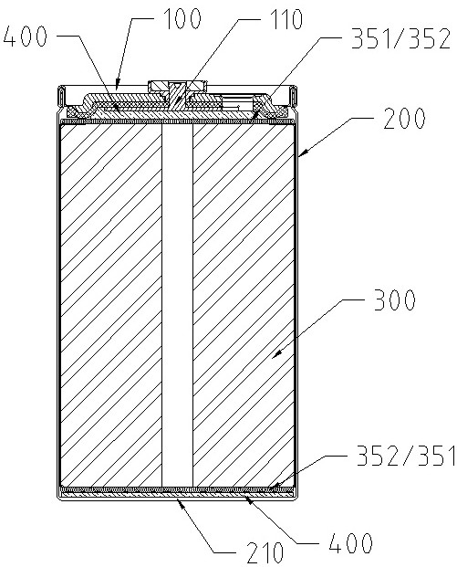
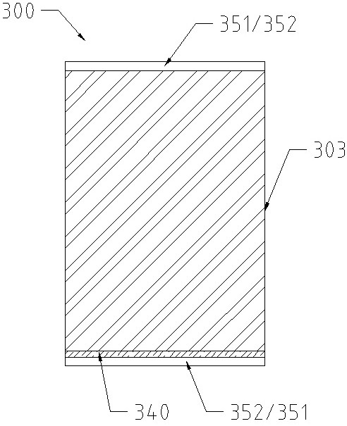
[0036] Such as Figure 1-2 As shown, a cylindrical electric core adopting non-welding conductive connection, which includes a cover 100, a casing 200, a winding core 300 and a conductive glue 400, and the winding core 300 contained in the casing 200 is composed of a negative electrode sheet 301, The positive electrode sheet 303, the first separator 302 and the second separator 304 are wound, and the negative electrode sheet 301 leaks outside the adjacent separator. The fluid 352 is electrically connected to the adjacent housing bottom 210 through the conductive glue 400. The positive electrode sheet 303 leaks to the adjacent separator. 351 is electrically connected to the adjacent pole contact surface 110 through the conductive glue 400 .

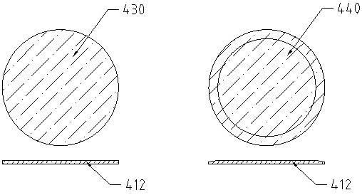
[0037] For a better effect, the conductive glue 400 connected to the bottom of the housing 210 is the shell bottom conductive glue 430, the conductive glue 400 connected to the pole contact surface 110 is the pole conductive glue 440, and ...

Embodiment 2

[0052] Such as Figure 1-2 As shown, a cylindrical electric core adopting non-welding conductive connection, which includes a cover 100, a casing 200, a winding core 300 and a conductive glue 400, and the winding core 300 contained in the casing 200 is composed of a negative electrode sheet 301, The positive electrode sheet 303, the first separator 302 and the second separator 304 are wound, and the negative electrode sheet 301 leaks outside the adjacent separator. The fluid 352 is electrically connected to the pole contact surface 110 of the adjacent upper cover 100 through the conductive glue 400, and the positive electrode leakage current collector 351 of the positive electrode sheet 303 leaking from the adjacent diaphragm is located at the other end of the winding core 300. The positive electrode drain current collector 351 is electrically connected to the adjacent casing bottom 210 through the conductive glue 400 .

[0053] For a better effect, the conductive glue 400 co...

Embodiment 3

[0067] Such as Figure 1-2 As shown, a cylindrical electric core adopting non-welding conductive connection, which includes a cover 100, a casing 200, a winding core 300 and a conductive glue 400, and the winding core 300 contained in the casing 200 is composed of a negative electrode sheet 301, The positive electrode sheet 303, the first separator 302 and the second separator 304 are wound, and the negative electrode sheet 301 leaks outside the adjacent separator. The fluid 352 is electrically connected to the pole contact surface 110 of the adjacent upper cover 100 through the conductive glue 400, and the positive electrode leakage current collector 351 of the positive electrode sheet 303 leaking from the adjacent diaphragm is located at the other end of the winding core 300. The positive electrode drain current collector 351 is electrically connected to the adjacent casing bottom 210 through the conductive glue 400 .

[0068] For a better effect, the conductive glue 400 co...


PUM


Abstract

The invention relates to a cylindrical cell adopting non-welding conductive connection, which comprises an upper cover, a shell, a roll core and a conductive adhesive, the roll core accommodated in the shell is formed by winding a negative plate, a positive plate, a first diaphragm and a second diaphragm, the negative electrode leakage current collector of which the positive electrode plate is exposed out of the adjacent diaphragm is positioned at the one end of the roll core, the negative electrode leakage current collector is electrically connected with the adjacent bottom of the shell or the contact surface of the pole through a conductive adhesive, the positive electrode leakage current collector of which the positive electrode plate is exposed out of the adjacent diaphragm is positioned at the other end of the roll core, and the positive electrode leakage current collector is electrically connected with the adjacent contact surface of the pole or the bottom of the shell through a conductive adhesive; and the conductive adhesive is composed of an electric conductor and a bonding body which are located on the same layer. The invention also relates to a preparation method of the cylindrical battery cell adopting non-welding conductive connection. The method has the advantages that the safety performance of the battery cell is improved on the premise of not influencing the energy density of the battery cell, the low-voltage defect of the battery cell is improved, the manufacturing procedures are reduced, the equipment purchase and maintenance cost is reduced, and cost reduction and efficiency improvement are realized.

Description

technical field [0001] The invention belongs to the technical field of batteries, and in particular relates to a cylindrical electric core adopting non-welding conductive connection and a preparation method thereof. Background technique [0002] Traditional small cylindrical cells, new large cylindrical cells and large cylindrical cells with full lugs rubbed flat. Provide a current path, and the welding methods include resistance welding, ultrasonic welding and laser welding; among them, resistance welding is suitable for welding of many types of same or dissimilar metals, the process is simple, the heating time is short, and the welding deformation is small, but the equipment is expensive. The tensile strength and fatigue strength of the welding place are low, the needles are changed frequently, the welding area is limited by the space, and welding spatter and sparking may cause safety hazards such as short circuit of the battery cell; ultrasonic welding has good conductivi...

Claims


Application Information

Patent Timeline
Patent Type & Authority Applications(China)
IPC IPC(8): H01M50/514H01M50/531H01M10/04
CPCH01M50/514H01M50/531H01M10/04Y02E60/10Y02P70/50
Inventor 杲绍芒赵红娟许飞王昌权马红涛别深超许四龙葛增乐
Owner DO FLUORIDE NEW ENERGY TECHNOLOGY CO LTD
Learn More