Substrate treatment apparatus and substrate treatment method
a substrate treatment and treatment apparatus technology, applied in the direction of pretreated surfaces, coatings, basic electric elements, etc., can solve the problems of increasing the treatment cost, affecting the treatment effect, so as to achieve the effect of small thickness and reduced flow ra
- Summary
- Abstract
- Description
- Claims
- Application Information
AI Technical Summary
Benefits of technology
Problems solved by technology
Method used
Image
Examples
first embodiment
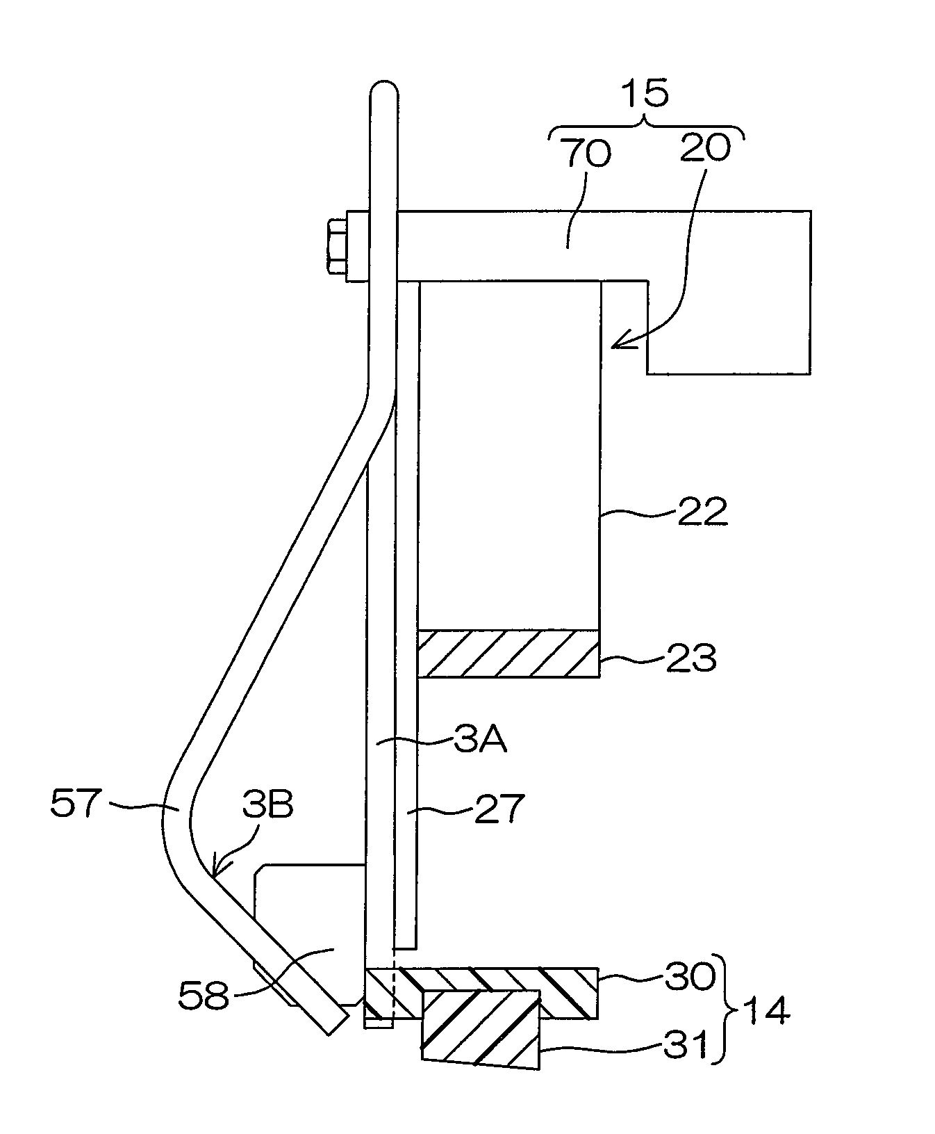
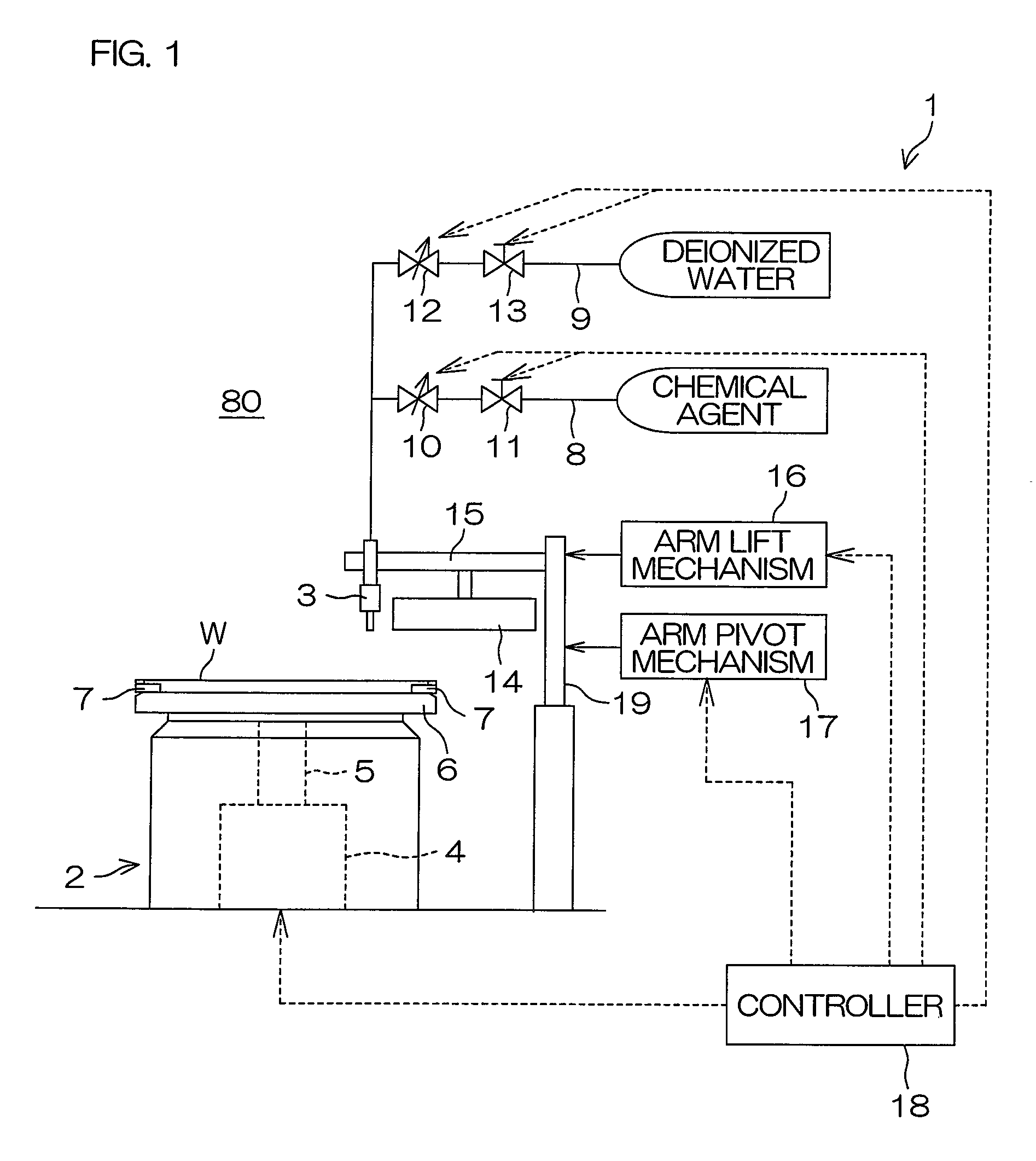
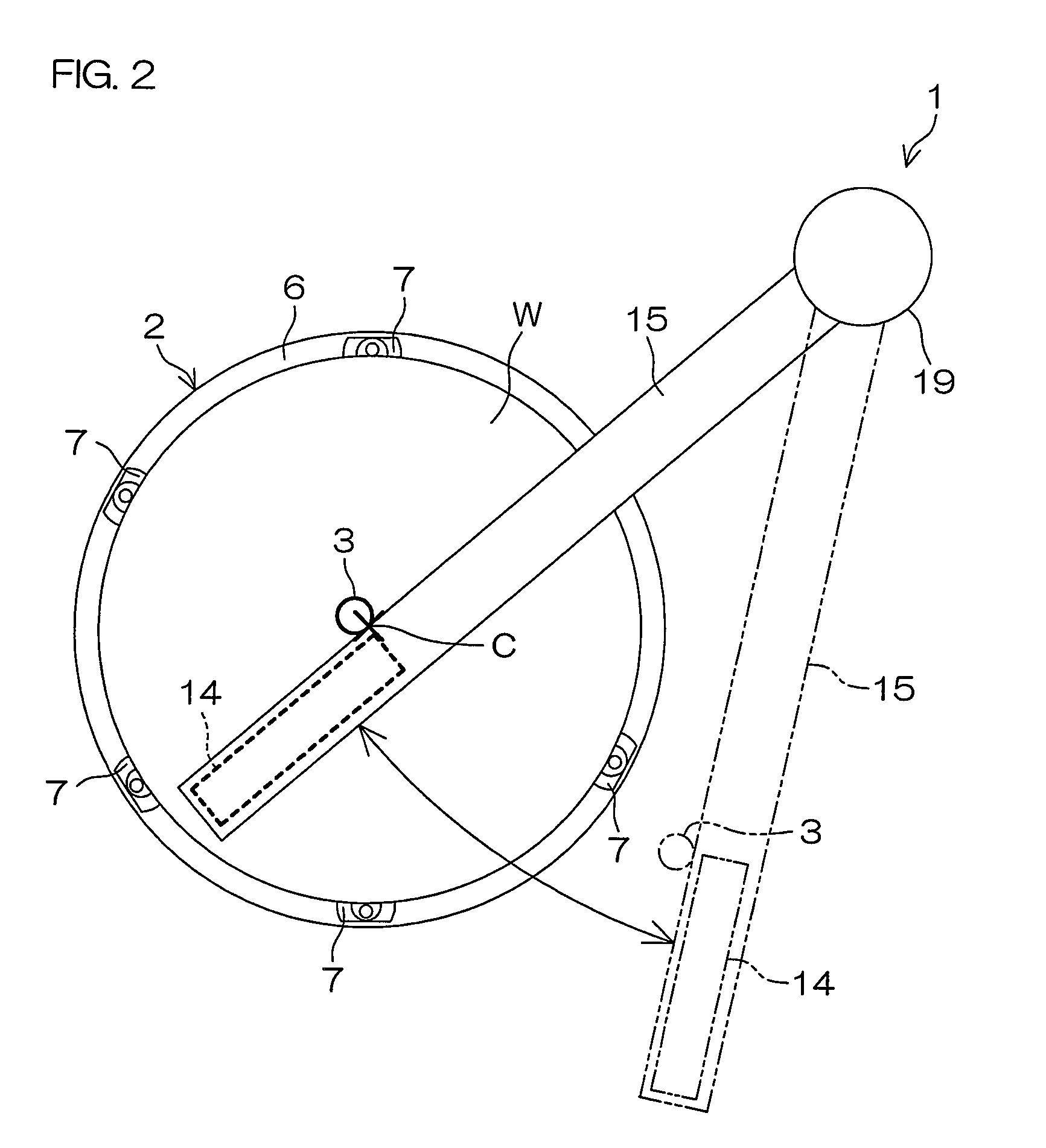
[0064]FIG. 1 is a diagram schematically showing the construction of a substrate treatment apparatus 1 according to one embodiment (first embodiment) of the present invention. FIG. 2 is a plan view showing the schematic construction of the substrate treatment apparatus 1.
[0065]The substrate treatment apparatus 1 is of a single substrate treatment type for treating a front surface of a semiconductor wafer (hereinafter referred to simply as “wafer”) W as an exemplary substrate with a treatment liquid (e.g., a chemical agent and deionized water).
[0066]The substrate treatment apparatus 1 includes a spin chuck (substrate holding unit) 2 which horizontally holds and rotates the wafer W, and a nozzle 3 which supplies the treatment liquid to an upper surface (front surface) of the wafer W held by the spin chuck 2. The spin chuck 2 and the nozzle 3 are provided in a treatment chamber 80 defined by a partition wall (not shown).
[0067]The spin chuck 2 includes a motor (rotating unit) 4, a spin s...
third embodiment
[0120]FIG. 11 is a diagram schematically showing the construction of a substrate treatment apparatus 201 according to further another embodiment (third embodiment) of the present invention.
[0121]The substrate treatment apparatus 201 is of a single substrate treatment type for performing a cleaning process for removing a contaminant from a wafer W with the use of a treatment liquid.
[0122]The substrate treatment apparatus 201 includes a spin chuck (substrate holding unit) 203 which horizontally holds and rotates the wafer W, a chemical agent nozzle 204 which spouts a chemical agent toward a front surface (upper surface) of the wafer W held by the spin chuck 203, and a deionized water nozzle 205 which supplies deionized water to the front surface of the wafer W held by the spin chuck 203. The spin chuck 203, the chemical agent nozzle 204 and the deionized water nozzle 205 are provided in a treatment chamber 202 defined by a partition wall (not shown).
[0123]The spin chuck 203 includes a...
fourth embodiment
[0170]FIG. 17 is a perspective view schematically showing the construction of a substrate treatment apparatus 240 according to still another embodiment (fourth embodiment) of the present invention. FIG. 18 is a sectional view schematically showing the construction of the substrate treatment apparatus 240 shown in FIG. 17.
[0171]The substrate treatment apparatus 240 of the fourth embodiment shown in FIGS. 17 and 18 differs from the substrate treatment apparatus 201 of the third embodiment in that a disk-shaped opposing plate 241 is provided instead of the bar-shaped opposing bar 220 as the opposing member.
[0172]The opposing plate 241 includes a cylindrical fixture portion 242 (see FIG. 18) provided about the rotation center axis of the wafer W, and a disk-shaped disk portion 243 having a center aligning with the rotation center of the wafer W. The fixture portion 242 is provided instead of the fixture portion 230 of the third embodiment, and fitted around and fixed to the outlet pipe ...
PUM
 Abstract
Description
Claims
Application Information
 - R&D
- Intellectual Property
- Life Sciences
- Materials
- Tech Scout
- Unparalleled Data Quality
- Higher Quality Content
- 60% Fewer Hallucinations
Browse by: Latest US Patents, China's latest patents, Technical Efficacy Thesaurus, Application Domain, Technology Topic, Popular Technical Reports.
© 2025 PatSnap. All rights reserved.Legal|Privacy policy|Modern Slavery Act Transparency Statement|Sitemap|About US| Contact US: help@patsnap.com


