
Motor controller

a technology of motor controller and control system, which is applied in the direction of underwater vessels, non-deflectable wheel steering, navigation instruments, etc., can solve the problems of consuming fuel in a more-or-less inefficient manner, and reducing the effective payload and/or the operating range of an aircraft, so as to reduce fuel costs, pollution and noise levels, and increase payload capacity and/or range. , the effect o

Active Publication Date: 2014-11-25
BOREALIS TECH LTD
View PDF8 Cites 5 Cited by
  • Summary
  • Abstract
  • Description
  • Claims
  • Application Information

AI Technical Summary

Benefits of technology

[0008]Technical advantages of the present invention include: allowing the aircraft to taxi at an airport without the use of main engines or a tug; reducing fuel costs, pollution and noise levels; increasing payload capacity and / or range; and placing aircraft completely under pilot control thereby saving money and simplifying logistics.

Problems solved by technology

Use of the main engines consumes fuel in a more-or-less inefficient manner, creates pollution (atmospheric and noise), and reduces the effective payload and / or the operating range of an aircraft.
Use of a tug reduces pilot control, increases operating costs, and adds to the logistical complexity of airport operations.

Method used


Image

  • Motor controller
  • Motor controller
  • Motor controller

Examples


Embodiment Construction

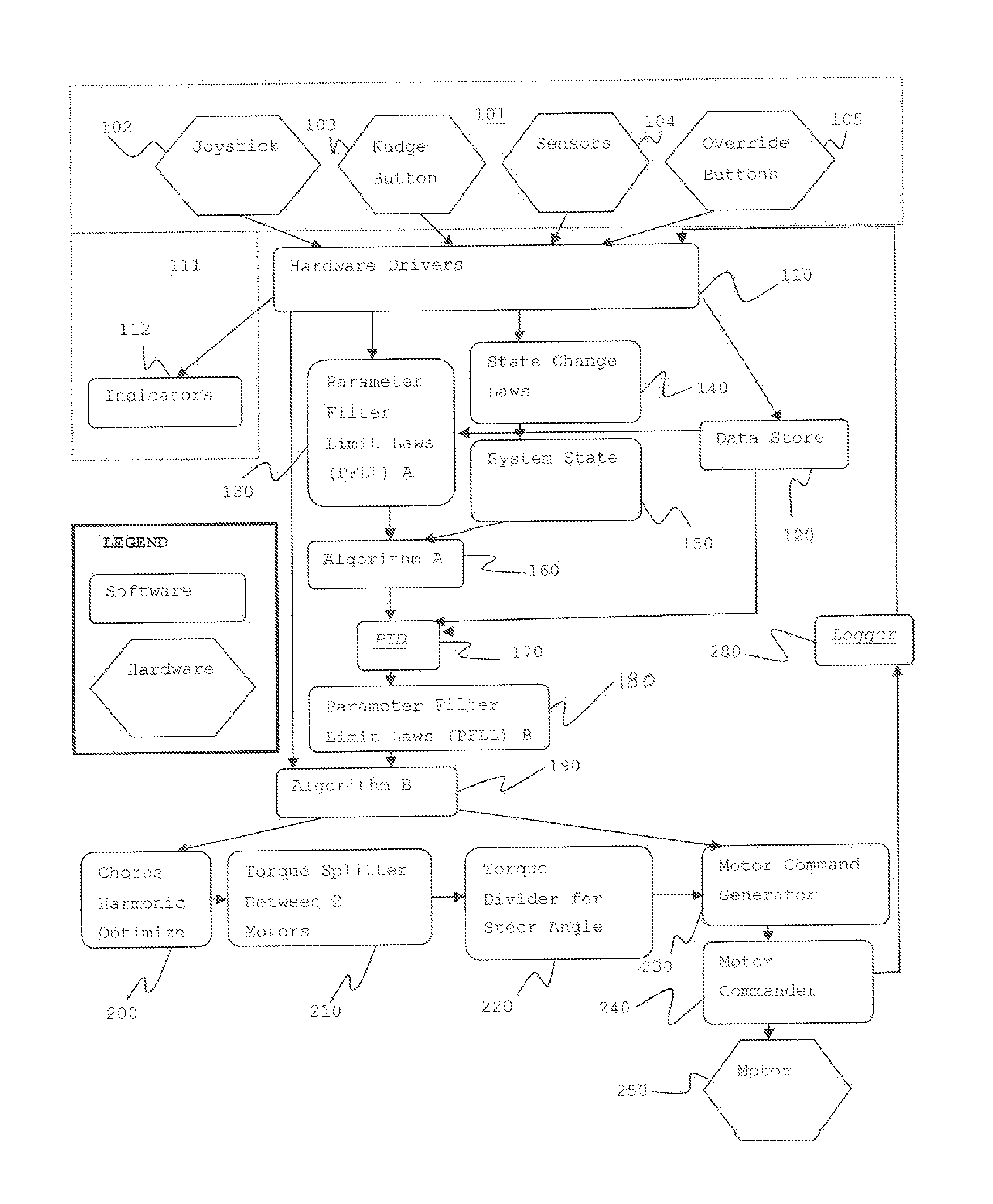
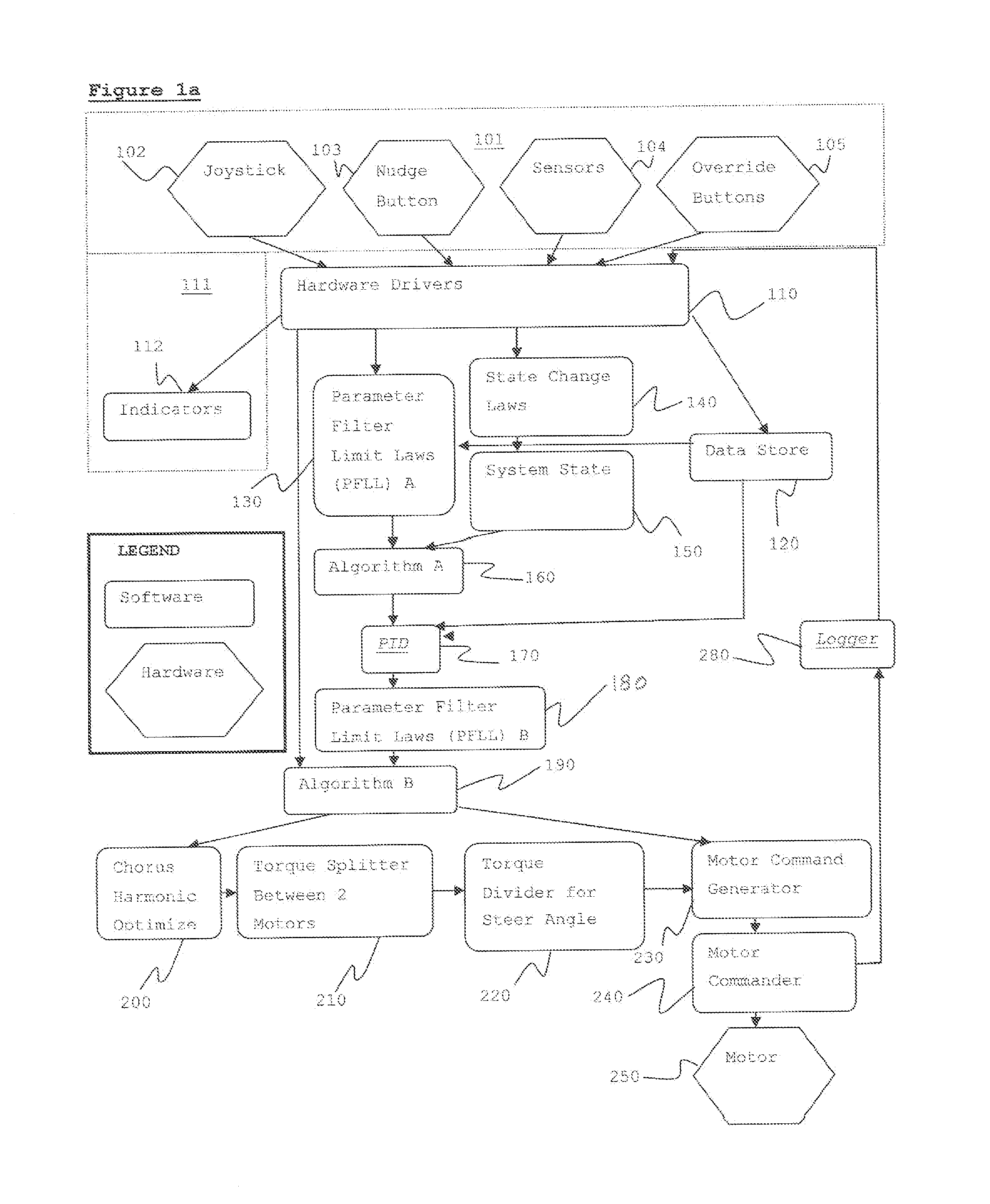
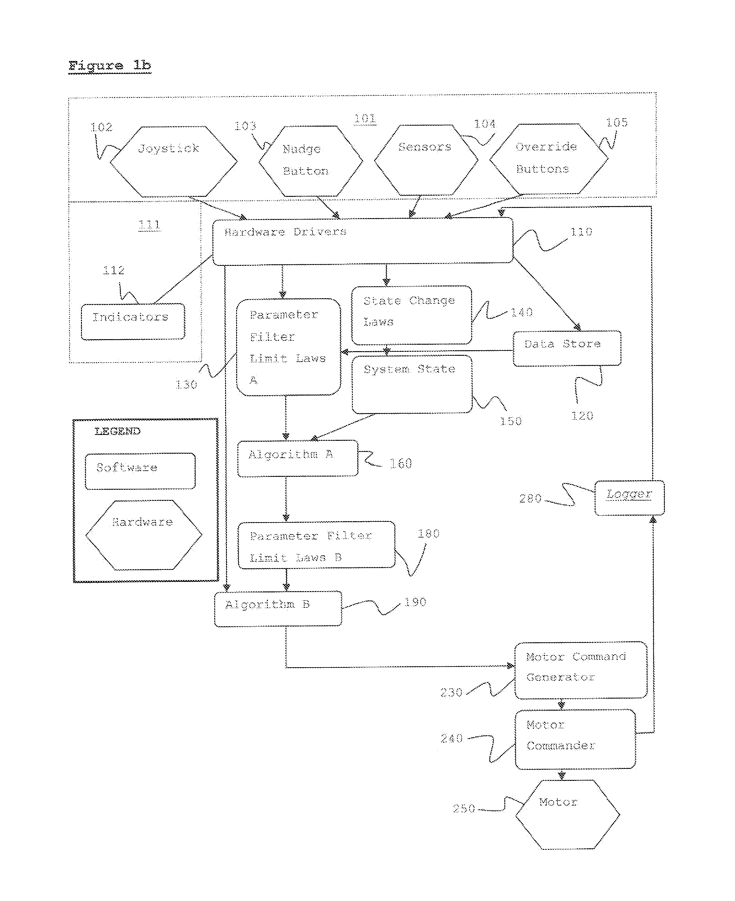
[0015]Referring now to FIG. 1a, a schematic of one preferred embodiment of the present invention is shown. A Pilot Interface includes various Input Devices 101 to provide input for the control system. Input Devices 101 include, but are not limited to, Joystick 102, Nudge Button 103, Sensors 104, and Override Buttons 105. Input Devices 101 allow the pilot to perform a number of actions, which may include but are not limited to: pull joystick forward; pull joystick backward; return joystick to neutral position; “nudge” forward; and safety override of motor heating actions.

[0016]Hydraulic brakes are an independent, mechanical, control input device that a pilot may use to stop or steer the wheels. Hydraulic brakes work independently to the electronic motor control system. It is nevertheless necessary that a reading of the hydraulic brake position should be made available to the software. In addition, a registration of a command to brake applied to the motor control software, may be acti...


PUM


Abstract

This application describes the software invented to control an electric motor system. The electric motor system is mounted on one or more aircraft main wheels or nose wheels to drive an aircraft independently on the ground without aircraft engines or tow vehicles. The software uses closed-loop control together with several other control laws to operate the drive motor or motors. Knowledge of the current operating state of the drive motor, together with knowledge of the commands given to taxi forward, taxi in reverse, or brake in reverse, is used to configure the motors to optimal operating parameters. The software architecture is described along with the pilot interface and many details of software implementation.

Description

[0001]This application is a continuation-in-part of U.S. patent application Ser. No. 11 / 885,388, filed on Aug. 29, 2007, and PCT Application No. PCT / US / 2006 / 007404 filed on Aug. 29, 2007, and based on U.S. Provisional Patent Application No. 60 / 657,633, filed on Mar. 1, 2005TECHNICAL FIELD[0002]This invention relates generally to a motor control system and specifically to a motor control system designed to control one or more motors mounted on an aircraft drive wheel to move the aircraft independently on the ground without the use of engines or tow vehicles.BACKGROUND ART[0003]In U.S. Pat. Nos. 6,657,334 and 6,831,430, a high phase order induction machine drive system is disclosed. This has an inverter system for the synthesis of a plurality of phases of alternating current output, and an N-phase induction motor (N is greater than 3). The motor is connected to the inverter terminals in the following way: each motor phase is electrically connected to two inverter terminals: a first in...

Claims


Application Information

Patent Timeline
Patent Type & Authority Patents(United States)
IPC IPC(8): B64C25/40B64C25/00G06F17/00G05D1/00G05D1/02
CPCB64C25/405G05D1/02Y02T50/823Y02T50/80
Inventor BAYER, JANICE, ILENE
Owner BOREALIS TECH LTD
Learn More