
Metal-air low temperature ionic liquid cell

a low temperature ionic liquid cell and metal-air technology, applied in the field of electrochemical metal-air cells, can solve the problems of inoperable cells before the fuel consumption, significant limiting factors of metal-air batteries, and inability to operate effectively, so as to reduce gaseous oxygen

Active Publication Date: 2014-11-25
ARIZONA STATE UNIVERSITY
View PDF15 Cites 36 Cited by
  • Summary
  • Abstract
  • Description
  • Claims
  • Application Information

AI Technical Summary

Benefits of technology

The present invention provides an electrochemical metal-air cell that uses a low temperature ionic liquid as an ionic conductor for supporting the reactions at the fuel and air electrodes. The cell has a flexible fuel electrode and air electrode arranged in a compact non-linear configuration, which allows for absorbing gaseous oxygen and reducing it to oxygen gas. The ionic liquid is contained in a space between the electrodes and conducts ions for supporting the reactions. The cell operates at or below 150°C and has a vapor pressure above its melting point. The technical effects of this invention include improved performance and efficiency of the electrochemical metal-air cell, as well as flexibility and compact design for the fuel and air electrodes.

Problems solved by technology

A significant limiting factor with metal-air batteries is the evaporation of the electrolyte solution, particularly the evaporation of the bulk solvent, such as water in an aqueous electrolyte solution.
Over time, the cell becomes incapable of operating effectively because of this issue.
Indeed, in many cell designs this evaporation issue renders the cell inoperable before the fuel is consumed.
Also, in rechargeable cells the water solvent is typically oxidized to evolve oxygen during re-charge, which may also deplete the solution.
However, either approach adds significantly to both the overall size of the cell, as well as the weight of the cell, without enhancing the cell performance (except to ensure that there is a sufficient volume of electrolyte solution to offset evaporation of the water or other solvent over time).
But the volume of electrolyte solution in the cell generally does not have a significant beneficial effect on cell performance, and thus generally only detracts from cell performance in terms of volumetric and weight based ratios (power to volume or weight, and energy to volume or weight).
Also, an excessive volume of electrolyte may create a higher amount of spacing between the electrodes, which may increase ionic resistance and detract from performance.

Method used


Image

  • Metal-air low temperature ionic liquid cell
  • Metal-air low temperature ionic liquid cell
  • Metal-air low temperature ionic liquid cell

Examples


Embodiment Construction

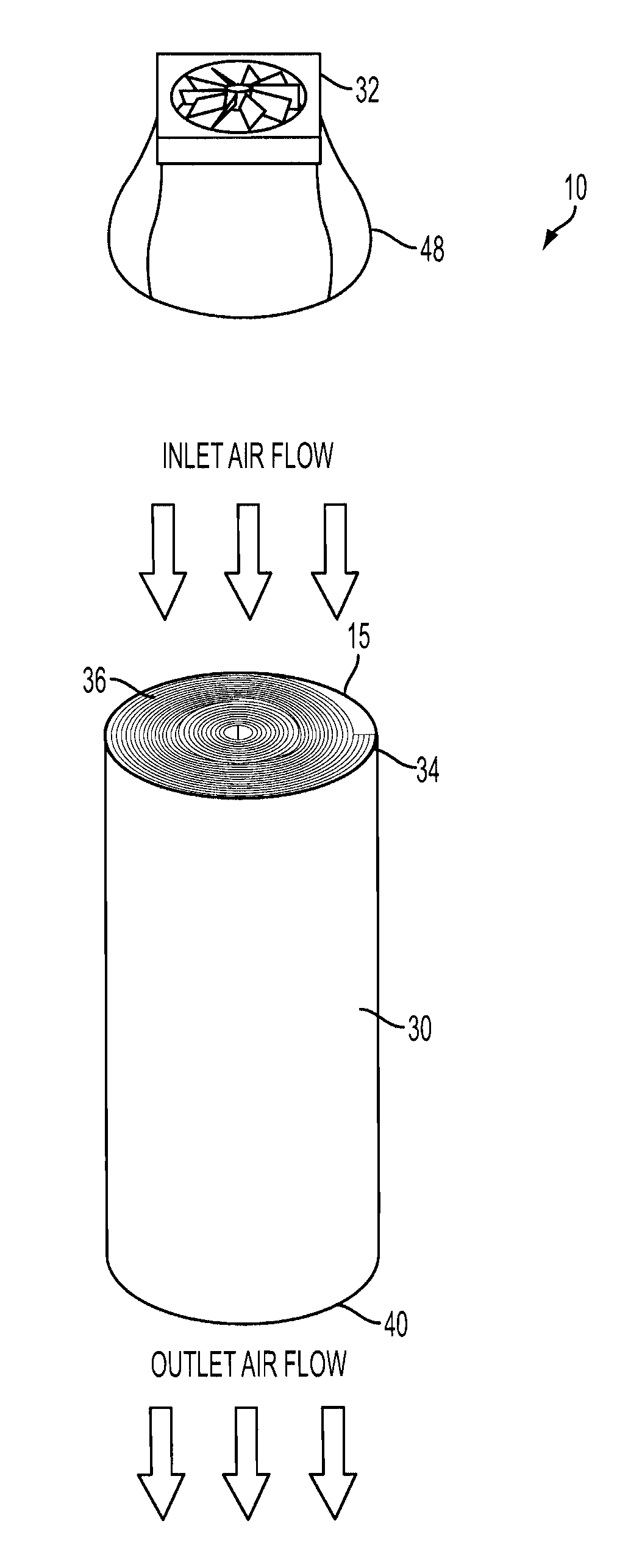
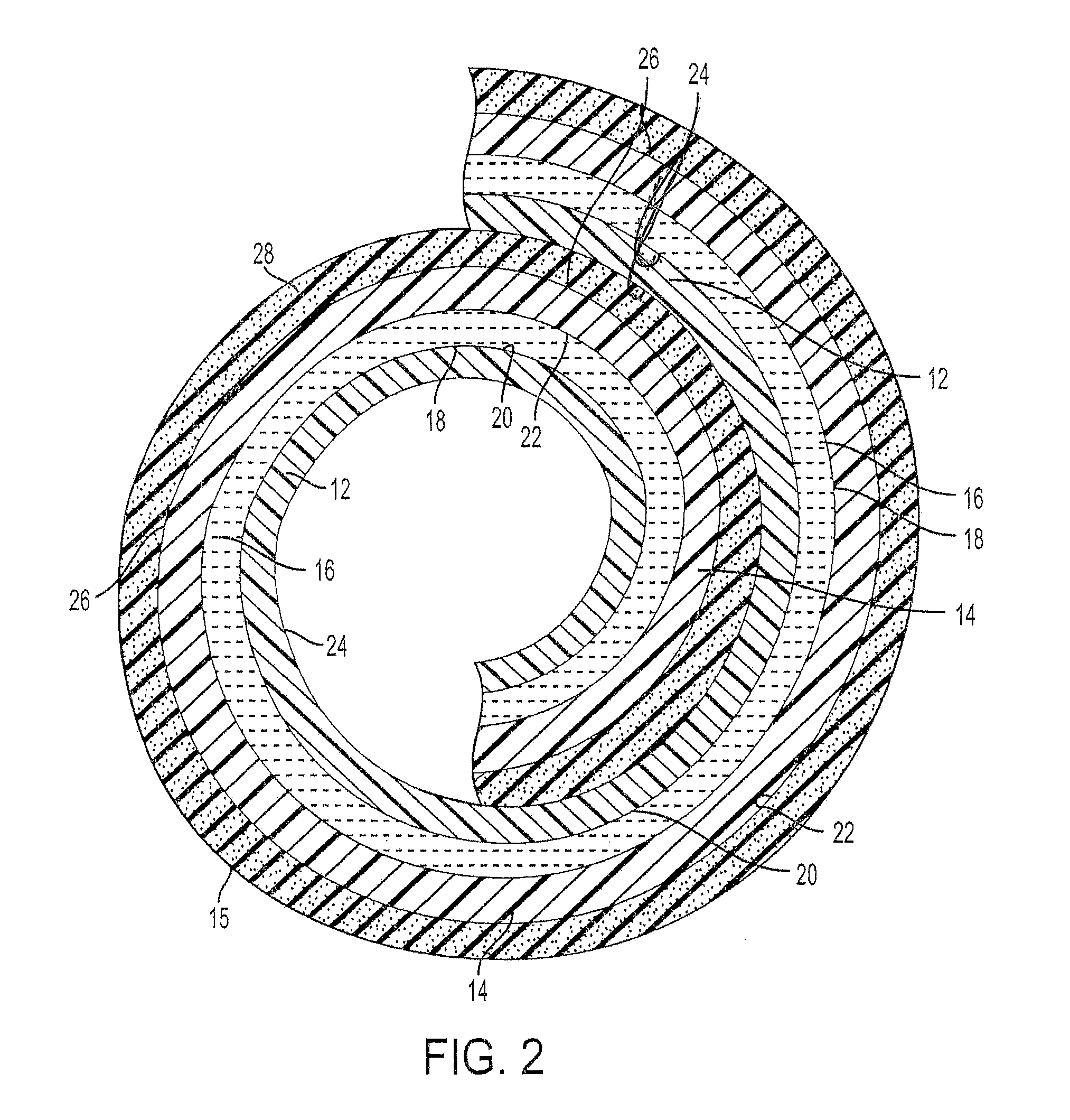
[0018]The present application discloses an electrochemical metal-air cell 10. The cell 10 may have any construction or configuration, and the example(s) described herein are not limiting. The cell 10 may be designed to have its electrodes arranged in a compact configuration, such as a roll configuration, as is shown in the Figures. In general, the cell 10 comprises a flexible fuel electrode 12 for receiving a metal fuel, a flexible air electrode 14, and an ionically conductive medium comprising a low temperature ionic liquid 16 (which may be a room temperature ionic liquid) contained in a space 18 between the flexible fuel electrode 12 and the air electrode 14. The ionic liquid 16 is in contact with internal surfaces 20, 22 of the fuel and air electrodes, respectively. In any architectural embodiment of the invention, the ionically conductive medium may be of any of the types mentioned herein.

[0019]In some non-limiting embodiments, a substance that may be regarded in some contexts a...


PUM

PropertyMeasurementUnit
melting pointaaaaaaaaaa
vapor pressureaaaaaaaaaa

Abstract

The present application relates to an electrochemical metal-air cell in which a low temperature ionic liquid is used.

Description

PRIORITY INFORMATION[0001]The present application claims priority to U.S. Provisional Application Ser. No. 61 / 177,072, filed May 11, 2009, and U.S. Provisional Application Ser. No. 61 / 267,240, filed Dec. 7, 2009, each of which is incorporated herein in their entirety.[0002]This invention was made with U.S. government support under Contract No. DB-AR-0000038 awarded by the Department of Energy. The government has certain rights in the invention.FIELD OF THE INVENTION[0003]The present application relates to an electrochemical metal-air cell in which a low temperature ionic liquid is used.BACKGROUND OF THE INVENTION[0004]Metal-air batteries typically include a fuel electrode at which metal fuel is oxidized, an air electrode at which oxygen is reduced, and an electrolyte solution for providing ion conductivity. A significant limiting factor with metal-air batteries is the evaporation of the electrolyte solution, particularly the evaporation of the bulk solvent, such as water in an aqueo...

Claims


Application Information

Patent Timeline
Patent Type & Authority Patents(United States)
IPC IPC(8): H01M8/22
CPCH01M12/08H01M2300/0045H01M2300/0025H01M12/06Y02E60/10
Inventor FRIESEN, CODY A.BUTTRY, DANIEL A.
Owner ARIZONA STATE UNIVERSITY
Learn More