
Cell culture container and cell culture method using the container

a cell culture container and cell culture technology, applied in the field of cell culture containers, can solve the problems of inability to stably create an environment with a concentration gradient of oxygen, large capacity of conventional containers used for cell culture, etc., and achieve the effect of stably creating

Inactive Publication Date: 2013-06-27
SHIMADZU CORP +2
View PDF5 Cites 11 Cited by
  • Summary
  • Abstract
  • Description
  • Claims
  • Application Information

AI Technical Summary

Benefits of technology

The present invention is related to a cell culture container and method that allows for the stable creation of a desired environment for cell culture without subjecting the cells to unnecessary stress. By using a cell culture container with two gas-permeable membranes, one for a specific component and one for a non-specific component, a stable concentration gradient of the specific component can be formed in the liquid cell culture medium. The flow rates and concentrations of the gases can be adjusted to control the concentration gradient. Additionally, the cell culture method allows for the adjustment of the concentration of the specific component around the cell to create an environment close to an in-vivo environment.

Problems solved by technology

However, conventional containers such as petri dishes, flasks, and well plates generally used for cell culture are too large in capacity to form a concentration gradient of oxygen.
Further, a carbon dioxide incubator, a microscopic illumination lamp, a fluorescent lamp, and other electric devices are present as heat sources, and therefore, movement of a liquid (in this case, a culture medium) is caused mainly by heat convection, which makes it impossible to stably create an environment having a concentration gradient of oxygen.

Method used


Image

  • Cell culture container and cell culture method using the container
  • Cell culture container and cell culture method using the container
  • Cell culture container and cell culture method using the container

Examples


Embodiment Construction

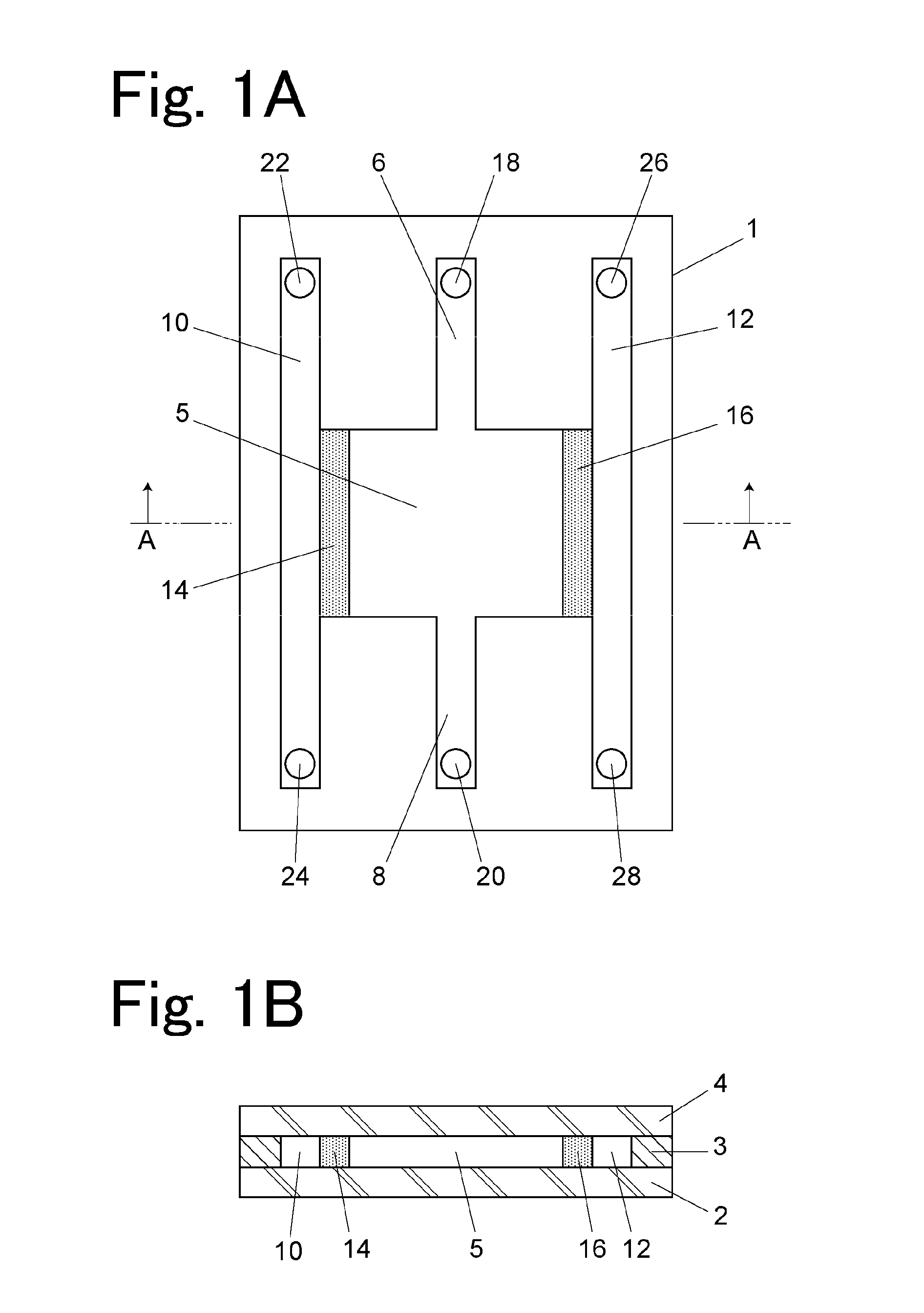
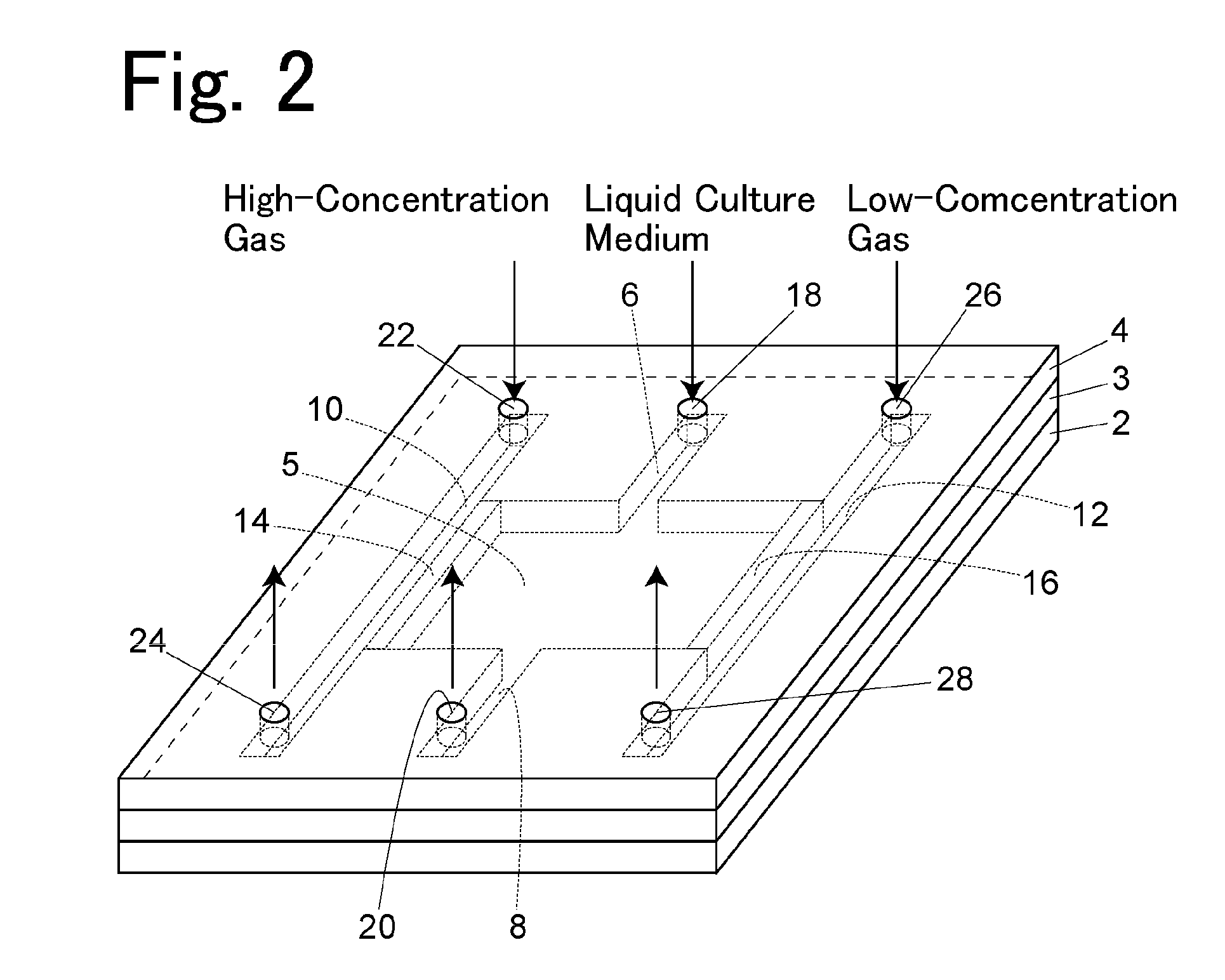
[0037]An embodiment of a cell culture container will be described with reference to FIGS. 1 and 2.

[0038]A cell culture container 1 according to this embodiment includes a well 5, a first channel 10, and a second channel 12 provided inside thereof. The well 5 is a rectangular parallelepiped space and has a pair of opposed side surfaces, one of which is in contact with a compartment of the first channel 10 with a gas-permeable membrane 14 being interposed therebetween, and the other of which is in contact with a compartment of the second channel 12 with a gas-permeable membrane 16 being interposed therebetween. The gas-permeable membranes 14 and 16 are membranes permeable to gas but not permeable to liquid. The well 5 has another pair of side surfaces, one of which is provided with a channel 6 for introducing a liquid cell culture medium, and the other of which is provided with a discharge channel 8.

[0039]The cell culture container 1 is formed by integrating two transparent substrates...


PUM


Abstract

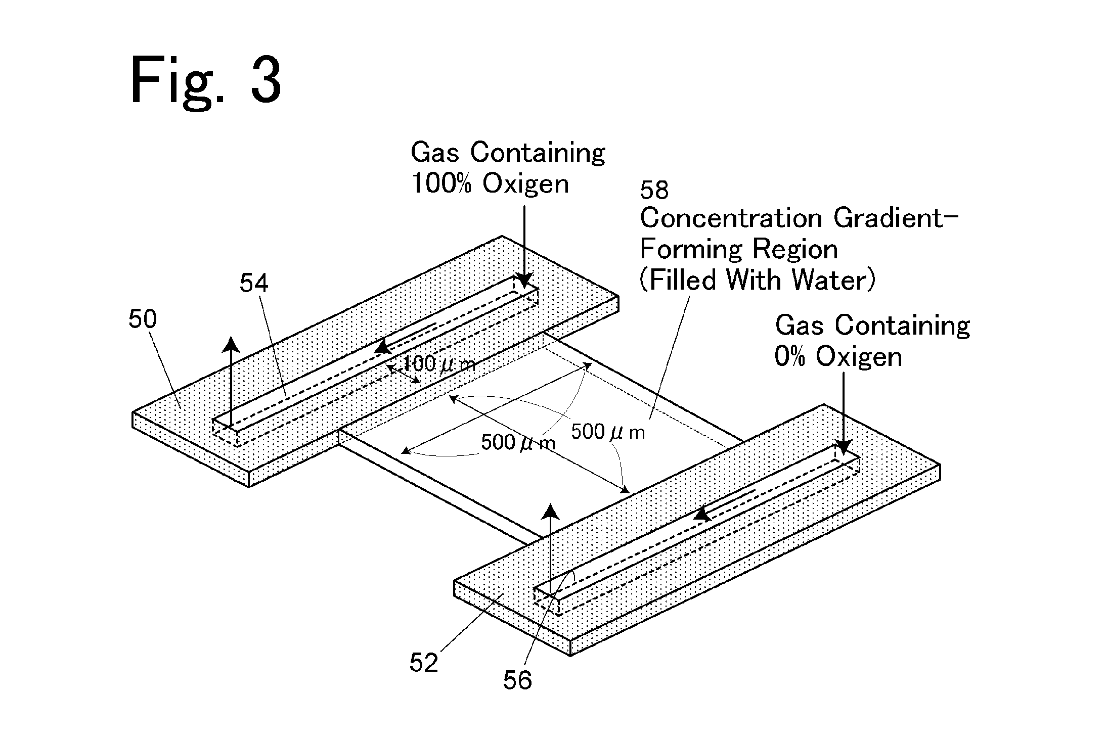
A well has a pair of side surfaces, and one of the side surfaces is in contact with a compartment of a first channel with a gas-permeable membrane being interposed therebetween and the other side surface is in contact with a compartment of a second channel with a gas-permeable membrane being interposed therebetween. The well is filled with a liquid cell culture medium, and in such a state, a high-concentration gas and a low-concentration gas, which are different in the concentration of a specific component from each other, are allowed to flow through the first and second channels, respectively, to form a concentration distribution of the specific component in the well.

Description

TECHNICAL FIELD [0001]The present invention relates to a cell culture container that has a well for cell culture and is intended to create an environment suitable for cell culture in the well and a cell culture method using the container. Such a cell culture container is used to, for example, simulate an in-vivo microenvironment to analyze the functions of cells or the efficacy of a drug against cells.BACKGROUND ART [0002]In the living body, oxygen and nutrition are sufficiently supplied to normal tissues through blood vessels. On the other hand, it is said that tumor tissues are under low-oxygen and low-nutrient conditions because vascularization does not occur in proportion to the growth of cancer cells or each vascular structure is disordered and fragile. Such a relation between cancer and low oxygen and nutrient concentrations has been discussed, but recently has been particularly actively studied. For example, it has hitherto been found that some cancer cells have become resis...

Claims


Application Information

Patent Timeline
IPC IPC(8): C12M1/00C12N5/074
CPCC12M23/12C12M23/24C12M23/04C12N5/0607C12M29/00
Inventor MUNAKA, TATSUYAABE, HIROHISAKANAI, MASAKIAKECHI, MASAKAZUMAEKAWA, TAIRAKIMURA, SHINYAASIHARA, EISHISHOJI, SHUICHIKAWAI, KENTARO
Owner SHIMADZU CORP
Learn More