Memory system and memory chip

a memory system and memory chip technology, applied in the field of memory, can solve the problems of inability to recognize the power consumption of the memory, the power consumption of the controller also varies between operations, and the power consumption of the sequence which is executed

Inactive Publication Date: 2014-11-18
KK TOSHIBA
View PDF38 Cites 8 Cited by
  • Summary
  • Abstract
  • Description
  • Claims
  • Application Information

AI Technical Summary

Benefits of technology

[0039]Specific advantageous effects of the memory system 1 according to the first embodiment will now be described.
[0040]FIG. 2 is a timing chart showing an example of the relationship between a memory system operation and a power consumption in a typical example.
[0041]As shown in FIG. 2, if the process of the controller overlaps the busy state of the memory, there is a case in which the peak of the memory power consumption overlaps the peak of the controller power consumption. If these peaks overlap, the peak of the system power consumption sharply rises, as indicated by an arrow A. This may lead to an increase in battery power consumption or to malfunction due to power consumption exceeding the battery capacity. However, even if the memory is in the busy state, the process of the controller progresses, and thus the process speed of the memory system is high.
[0042]FIG. 3 is a timing chart showing another example of the relationship between the memory system operation and the power consumption in the typical example.
[0043]The ready / busy output RY / / BY is provided in the memory system. It is thinkable that the process of the controller is halted while the memory is in the busy state, as shown in FIG. 2, by making use of the ready / busy output RY / / BY. In the busy state, the process of the controller is halted. Thus, the peak of the memory power consumption does not overlap the peak of the controller power consumption. In this example, the peak of the system power consumption does not sharply rise. However, since the process of the controller is halted while the memory is in the busy state, the process speed of the memory system is low.
[0044]FIG. 4 is a timing chart showing an example of the relationship between the memory system operation and the power consumption in the first

Problems solved by technology

In the case of a memory, such as a flash memory, which executes an internal operation by an Auto command, a plurality of sequences are executed in series or in parallel in an Auto operation, and the amount of power consumption varies between the sequences which are executed.
The power consumption of the controller also varies between operations.
The controller side can recognize the power consumption in each operation of the controller itself, but cannot recognize the power consumption of the memory that is in the Auto operation.
Thus, there is a tendency that a peak of large power consumption of the memory system may easily rise.

Method used


Image

  • Memory system and memory chip
  • Memory system and memory chip
  • Memory system and memory chip

Examples


first embodiment

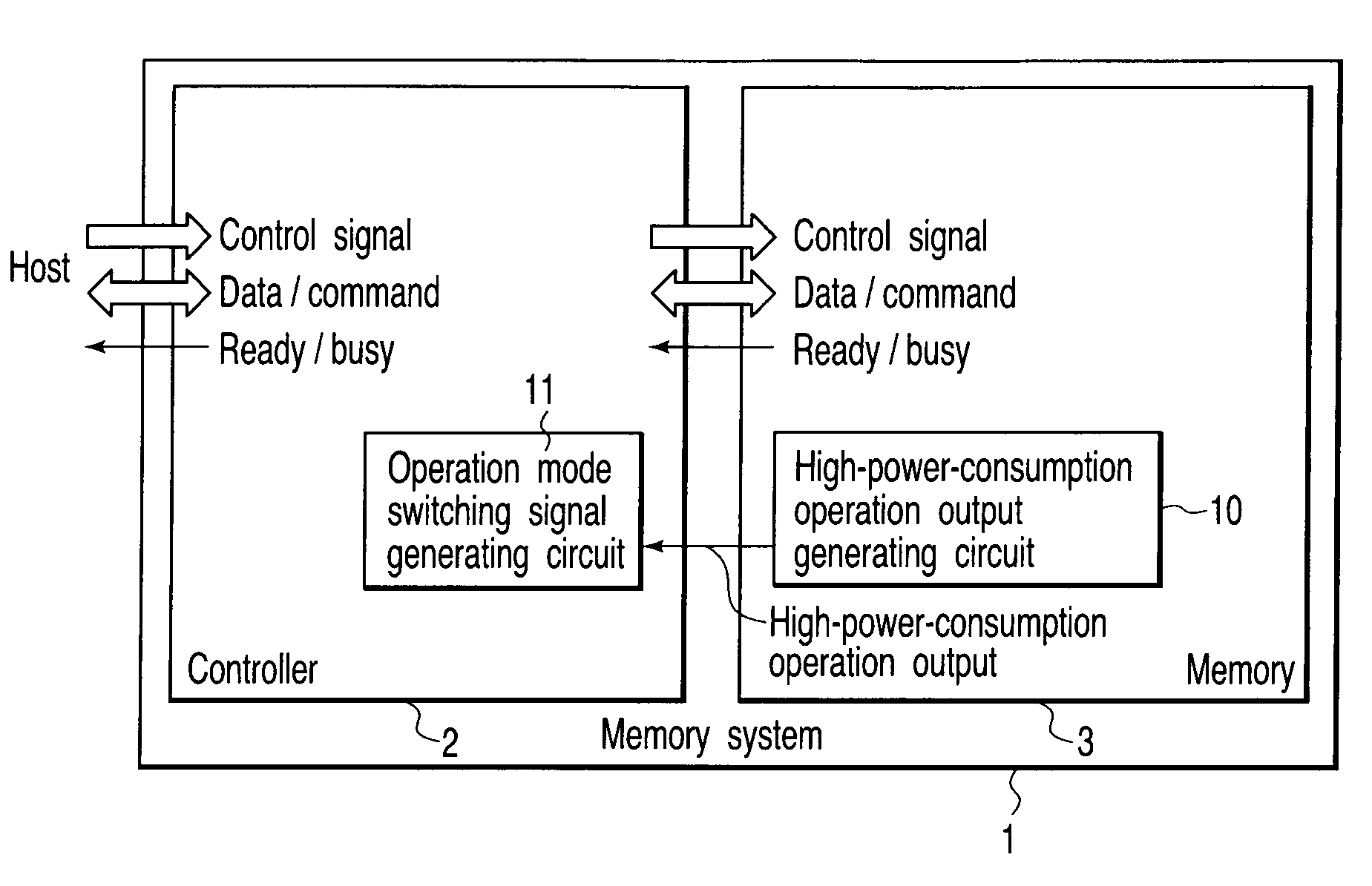
[0032]FIG. 1 is a block diagram showing a basic structure of a memory system according to a first embodiment of the present invention.

[0033]As shown in FIG. 1, a memory system 1 according to the first embodiment includes a controller 2 and a memory 3 which is controlled by the controller 2. An example of the memory 3 is a nonvolatile semiconductor memory. An example of the nonvolatile semiconductor memory is a flash memory. An example of the flash memory is a NAND flash memory. A specific example of the memory system 1 is a memory card. The memory card is used as a recording medium for, for instance, a digital camera, a mobile phone and a portable music player.

[0034]The memory 3 in this embodiment receives a control signal, write data and a command from the controller 2. The memory 3 outputs read data and ready / busy output (RY / BY) to the controller 2. Examples of the control signal are a chip enable / CE (“ / ” indicates a negative logic), a write enable / WE, a read enable / RE, a comma...

second embodiment

[0081]A second embodiment is an example relating to an output method of the high-power-consumption operation output.

[0082]FIG. 9 is a circuit diagram showing a first example of a memory system according to the second embodiment of the invention.

[0083]As shown in FIG. 9, the memory system 1 includes a high-power-consumption operation output line which transmits the high-power-consumption operation output from the memory 3 to the controller 2.

[0084]The memory 3 shown in FIG. 9 drives the high-power-consumption operation output line when the high-power-consumption operation output is asserted, and sets the power-consumption operation output line at a high impedance when the high-power-consumption operation output is negated, or vice versa. FIG. 9 shows the former by way of example.

[0085]Specifically, the output of the high-power-consumption operation output generating circuit 10 is supplied to the gate of an N-channel insulated-gate FET 30. The FET 30 drives the high-power-consumption ...

third embodiment

[0098]FIG. 14 is a block diagram showing an example of a memory system according to a third embodiment of the invention.

[0099]As shown in FIG. 14, in the third embodiment, the level of the high-power-consumption operation can be selectively set in the memory 3 by an instruction from the controller 2. Specifically, the level of the power consumption value for distinguishing “assert” and “negate” of the high-power-consumption operation output is set from the outside. The set level of the power consumption value is stored in a power consumption boundary setting register 50 of the memory 3. A sequence state discrimination circuit 51 discriminates the sequence state, and detects or estimates the value of the power consumption of the memory 3. The level, which is stored in the power consumption boundary setting register 50, is supplied to the sequence state discrimination circuit 51. The sequence state discrimination circuit 51, for example, compares the supplied level and the detected or...


PUM


Abstract

A memory system includes a memory which asserts a high-power-consumption operation output when an amount of the power consumption is high in internal operations in respective operations, and a controller which has an interface function between a host and the memory and receives the high-power-consumption operation output. The controller switches an operation mode thereof to a low power consumption mode when the high-power-consumption operation output is asserted.

Description

CROSS-REFERENCE TO RELATED APPLICATIONS[0001]This is a Continuation application of PCT Application No. PCT / JP2007 / 065321, filed Jul. 31, 2007, which was published under PCT Article 21(2) in English.[0002]This application is based upon and claims the benefit of priority from prior Japanese Patent Application No. 2006-211198, filed Aug. 2, 2006, the entire contents of which are incorporated herein by reference.BACKGROUND OF THE INVENTION[0003]1. Field of the Invention[0004]The present invention relates to a memory, such as a flash memory, which executes an internal operation by, e.g. an Auto command, and to a memory system and a memory chip, which include the memory.[0005]2. Description of the Related Art[0006]In the case of a memory, such as a flash memory, which executes an internal operation by an Auto command, a plurality of sequences are executed in series or in parallel in an Auto operation, and the amount of power consumption varies between the sequences which are executed.[000...

Claims


Application Information

Patent Timeline
Patent Type & Authority Patents(United States)
IPC IPC(8): G06F1/32G06F1/26
CPCY02B60/32G06F1/3225Y02B60/1221Y02B60/1225G06F1/3275G06F1/3237G06F3/0625G06F3/0634G06F2206/1014G06F3/0679Y02B60/1228G06F1/3293Y02D10/00Y02D30/50G11C5/14G11C7/10Y02B70/10Y02B70/30
Inventor SUKEGAWA, HIROSHI
Owner KK TOSHIBA
Why Eureka
Try Eureka