
Method and apparatus for control battery and specification determining method of battery

a technology of specification determination and battery, which is applied in the direction of process and machine control, greenhouse gas reduction, instruments, etc., can solve the problems of inability to perform an appropriate control at all times according to load variations, high cost of battery and control apparatus, so as to reduce the capacity of the battery and reduce the cost of the battery

Active Publication Date: 2014-09-09
HITACHI LTD
View PDF31 Cites 1 Cited by
  • Summary
  • Abstract
  • Description
  • Claims
  • Application Information

AI Technical Summary

Benefits of technology

The invention provides a battery control system that can minimize fluctuations in power output by controlling interconnected distribution systems and generators. The system can extract only the intermediate-cycle components that are relevant to battery control, allowing for efficient control of the batteries. Additionally, the invention allows for battery control based on location and can reduce the capacity of the battery while still producing suitable specifications. Overall, the invention is a cost-effective solution for controlling batteries in power generation systems.

Problems solved by technology

To compensate for the short-cycle fluctuations that change in relatively short cycles, a fast response is required of control, tending to make the battery and the control apparatus expensive.
For the long-cycle fluctuations that change in relatively long cycles, the battery is required to have a correspondingly large capacity, which in turn tends to make the battery expensive.
Another drawback of the conventional technology described above is its inability to control the battery according to the battery installation location, making it impossible to perform an appropriate control at all times according to load variations.
A further drawback is that the above-mentioned conventional technology tends to make the battery capacity relatively large, with the result that appropriate battery specifications have not been able to be obtained.

Method used


Image

  • Method and apparatus for control battery and specification determining method of battery
  • Method and apparatus for control battery and specification determining method of battery
  • Method and apparatus for control battery and specification determining method of battery

Examples


Embodiment Construction

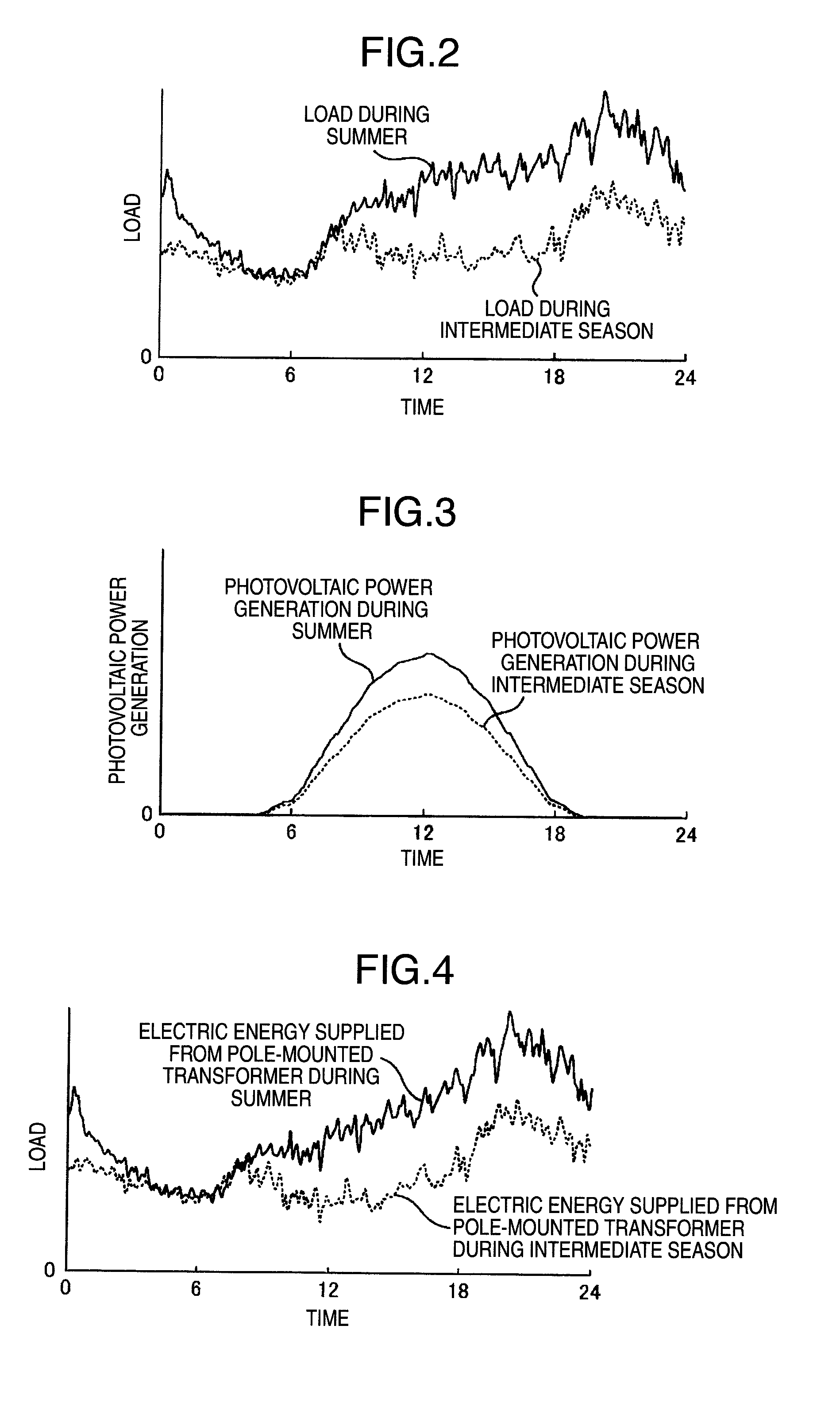
[0026]FIG. 1 shows a configuration of an optimal battery control system 10 for a distribution system as one embodiment of this invention. In FIG. 1, the optimal battery control system 10 comprises a battery 13 installed on a feeder 16 of a utility power distribution system, batteries 21, 22 installed between pole-mounted transformers 14, 15 and branch points of low-voltage power distribution lines 18, a communication network 8 to transmit data measured by meters 12, 23, 24, and a battery control quantity determination device 1 that determines a battery control quantity from the data acquired from the communication network.

[0027]The battery control quantity determination device 1 comprises: a load data collection unit 1-1 to gather an overall power data obtained by combining an energy demand of a plurality of loads 25, 26, 28, 29 and an output power of distributed generations 27, 30; a frequency conversion unit 1-2 to perform a frequency analysis based on the acquired load data; a BP...


PUM


Abstract

A battery control apparatus of this invention is provided which comprises: a battery installed on a feeder of a utility distribution system; batteries installed between pole-mounted transformers and branch points of the distribution lines; a communication network to transmit measurement data measured by meters; a battery control quantity calculation unit to determine battery control quantities from the measurement data acquired from the communication network; a load data collection unit to collect load data representing a combination of power consumption by a plurality of loads and generated power of distributed power generations; a frequency conversion unit to perform a frequency analysis on the load data; an intermediate-cycle component extraction unit to extract intermediate-cycle components; a battery control quantity calculation unit to determine battery control quantities from the extracted intermediate-cycle components; and a battery control command transmission unit to transmit the calculated control quantities to the batteries.

Description

BACKGROUND OF THE INVENTION[0001]The present invention relates to an apparatus and a method for controlling a battery and a battery specification determination method, and more specifically to a battery control apparatus and method and a battery specification determination method, both suitably used in a system connected with distributed power generations.[0002]Distributed generations such as photovoltaic power generation and wind power generation are currently drawing attention but the amount of electricity produced by these power generations is influenced by natural environments. To secure stability in power distribution systems by minimizing power flow variations caused by the distributed generations, a technology has been known which adjusts a demand / supply balance in the distribution systems by installing batteries on the terminal load side of pole-mounted transformers in the distribution system.[0003]One such technology has been known which controls the battery to reverse a st...

Claims


Application Information

Patent Timeline
Patent Type & Authority Patents(United States)
IPC IPC(8): G05D3/12H02J3/32H02J3/46H02J13/00
CPCH02J3/32H02J13/0006H02J3/46Y02E10/563Y02E70/30Y02E60/722Y04S10/14Y02E10/766Y02E10/763Y02E10/566Y04S10/123H02J13/00034Y02E60/00Y04S20/221Y04S20/222Y02B70/30Y02B70/3225H02J13/00002Y04S10/30Y02E10/56Y02E10/76
Inventor KIMURA, YASUTAKAWATANABE, MASAHIROSAWA, TOSHIYUKI
Owner HITACHI LTD
Learn More