
Method and apparatus for performing film thickness measurements using white light scanning interferometry

a technology of white light scanning and tomography, applied in the direction of instruments, spectral/fourier analysis, material analysis, etc., can solve the problems of limiting the measurement speed and lateral resolution, affecting the accuracy of film thickness measurements, and consuming the two-dimensional optimization process (h, d) time-consuming, etc., to achieve the effect of high film thickness accuracy

Active Publication Date: 2014-08-12
MITUTOYO CORP
View PDF12 Cites 2 Cited by
  • Summary
  • Abstract
  • Description
  • Claims
  • Application Information

AI Technical Summary

Benefits of technology

The present invention provides a method for faster measurements without the need for optimisation. The method uses a range of values determined by a preceding method to reduce the time-consuming step of optimisation. This method is particularly useful for thin film measurements as it can limit the searching range of the optimisation. The technical effect is the speeding up of the measurement process.

Problems solved by technology

Even though ellipsometry and reflectometry have been developed and improved with several techniques such as variable angles, polarizations and tuneable spectral bandwidth, however, they are typically based on a single point measurement which limits the measurement speed and lateral resolution.
However, two disadvantages to this approach are that the two-dimensional optimization process (h, d) is time consuming and setting the scanning range of h and d during the optimization makes real time measurements impossible.
However, in both cases, the preliminary experiments with the reflectance standard such as silicon show that these methods are limited due to their slow measurement speed and in its possible applications.

Method used


Image

  • Method and apparatus for performing film thickness measurements using white light scanning interferometry
  • Method and apparatus for performing film thickness measurements using white light scanning interferometry
  • Method and apparatus for performing film thickness measurements using white light scanning interferometry

Examples


Embodiment Construction

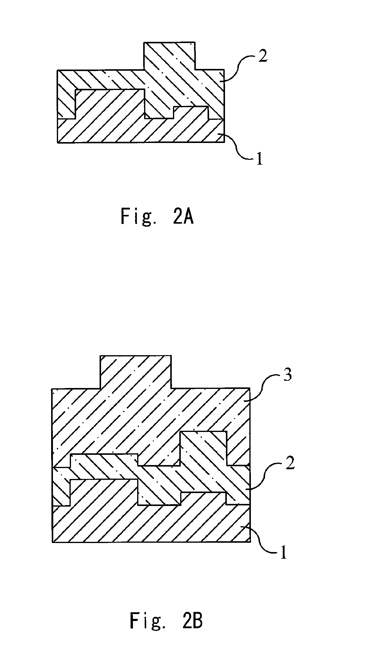
[0056]FIG. 2A shows a cross sectional view of a non-transparent substrate 1 onto which a semi-transparent film 2 has been provided. The present invention aims to measure the thickness of the film 2, initially independent from the height profile of the substrate 1, but in a special embodiment also together with the height profile.

[0057]Further, FIG. 2B shows a view similar to FIG. 2A, where a second semitransparent layer 3 has been applied on the first semitransparent layer 2. The refractive index of the second layer 3 is different from that of the first transparent layer 2.

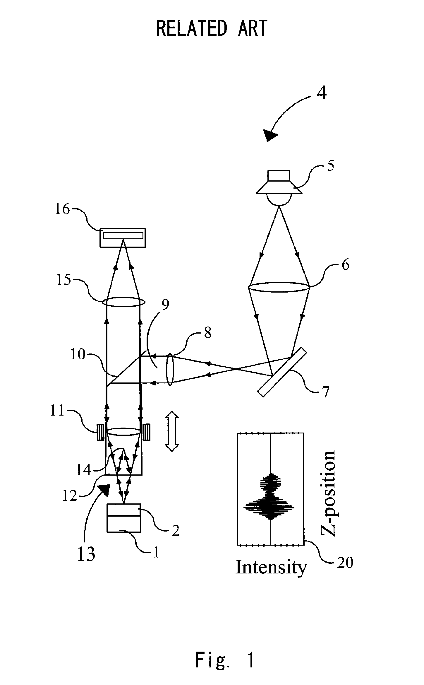
[0058]FIG. 1 depicts an interferometer of the Mirau type, denoted in its entirety by 4. This interferometer 4 comprises of a light source 5, adapted to generate white light, a first lens 6, a first mirror 7 and a second lens 8, these units being adapted to generate a parallel light beam 9. The parallel beam 9 may also be generated by other means. The parallel beam 9 is reflected by a beam splitter 10 and the refle...


PUM

PropertyMeasurementUnit
thicknessaaaaaaaaaa
thicknessaaaaaaaaaa
thicknessaaaaaaaaaa

Abstract

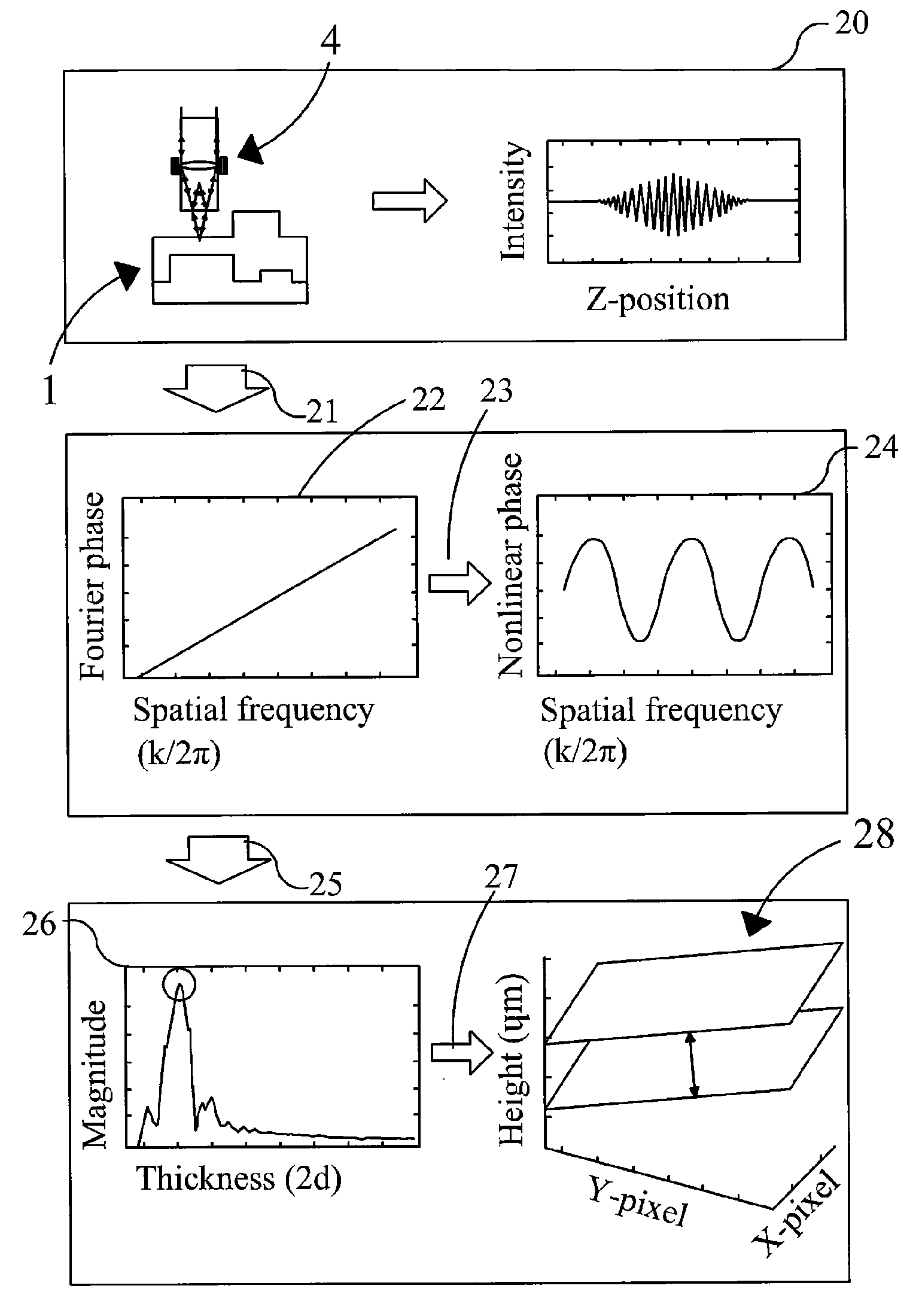
The invention relates to a method and an apparatus for measuring the thickness of a transparent film by broad band interferometry, comprising the steps of preparing a correlogram of the film by an interferometer, applying a Fourier transformation to said correlogram to obtain a Fourier phase function, removing a linear component thereof, applying a second integral transformation to the remaining non-linear component to obtain an integral amplitude function of said non-linear component, identifying the peak location of said integral amplitude function and determining the thickness of the film as the double value of the abscissa at said peak location considering a refractive index of a film which is dependent on wavelength. The last two steps may be replaced by identifying the peak locations of said integral amplitude function and determining the thickness of the films as the double values of the abscissas at the peak locations.

Description

INCORPORATION BY REFERENCE[0001]This application is a continuation-in-part (CIP) Application of commonly-assigned, co-pending, U.S. patent application Ser. No. 13 / 341,047, filed Dec. 30, 2011, which is based upon and claims the benefit of priority from European patent application No. 11152186.0, filed on Jan. 26, 2011, the disclosure of which is incorporated herein in their entirety by reference.BACKGROUND OF THE INVENTION[0002]1. Field of the Invention[0003]This invention is related to the high speed topographic surface and tomographic film thickness profile measurements using white light scanning interferometry.[0004]2. Description of Related Art[0005]It is well known in the science and industrial fields that ellipsometry and spectroscopic reflectometry can be used for highly accurate film thickness measurements. Even though ellipsometry and reflectometry have been developed and improved with several techniques such as variable angles, polarizations and tuneable spectral bandwidth...

Claims


Application Information

Patent Timeline
Patent Type & Authority Patents(United States)
IPC IPC(8): G01B11/02G01N21/41G01N21/43G01R23/16
CPCG01B11/0675
Inventor JOO, KI-NAM
Owner MITUTOYO CORP
Learn More