
Method and system for capturing carbon dioxide and/or sulfur dioxide from gas stream

a gas stream and carbon dioxide technology, applied in the field of emissions reduction, can solve the problems of inability to re-generate heat treatment, carbon sequestration costs, and formation of heat stable salts, and achieve the effects of reducing corrosive, avoiding amine evaporation, and improving absorption kinetics

Active Publication Date: 2014-07-08
RGT UNIV OF CALIFORNIA
View PDF33 Cites 4 Cited by
  • Summary
  • Abstract
  • Description
  • Claims
  • Application Information

AI Technical Summary

Benefits of technology

This approach significantly reduces the energy required for solvent regeneration, minimizes equipment corrosion, and allows for simultaneous CO2 and SO2 capture, potentially lowering the cost of electricity production and enhancing carbon sequestration efficiency.

Problems solved by technology

Thus, there is concern that the atmospheric temperature will rise to cause global climate change.
The largest costs in carbon sequestration are those associated with capturing and concentrating the carbon dioxide from the flue gas at the source.
In traditional amine or amino acid salt based CO2 scrubbing process, SO2 could be removed by a flue gas desulfurization (FGD) process first to avoid the reaction of SO2 with amine or amino acid salt, resulting in the formation of heat stable salts, which cannot be regenerated by heat treatment.
However, currently the state-of-the-art technologies for existing PC power plants are essentially limited to the solvent approach involving the use of amine absorbents.
However, the MEA process suffers many drawbacks if used for the capture of CO2 from coal-fired power plants.
), (3) low CO2 loading capacity (0.25-0.35 mol CO2 / mol MEA), (4) high absorbent makeup rate due to amine degradation by SO2, NOx, HCl and oxygen in flue gas, and (5) high equipment corrosion rate, particularly when a high concentration of MEA is used.
This disclosed method has the problem of plugging in the absorber.

Method used


Image

  • Method and system for capturing carbon dioxide and/or sulfur dioxide from gas stream
  • Method and system for capturing carbon dioxide and/or sulfur dioxide from gas stream
  • Method and system for capturing carbon dioxide and/or sulfur dioxide from gas stream

Examples


example 1

Ammonium Carbamate as Rate Promoter

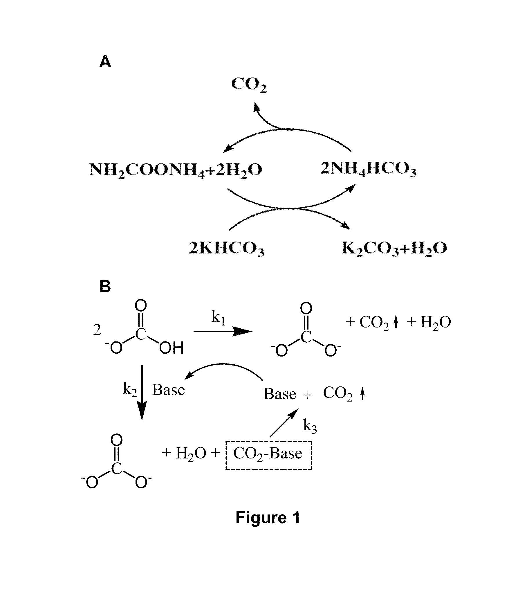
[0110]A novel stripping method for CO2 capture and regeneration from flue gas of the coal-fired power plant is introduced. With some rate promoters, such as ammonium carbamate, organic amines, or physical solvents, potassium bicarbonate slurry was converted to potassium carbonate solution by stripping. Both high temperature (as high as 120° C. by using high-pressure stripper) and low temperature (as low as 90° C. by using hot water) stripping conditions are discussed herein.

[0111]Ammonium carbamate was adopted as rate promoter because of its weak base nature. Briefly, there are three different stripping processes: ambient-pressure stripper only process; high-pressure stripper only process; and ambient-pressure and high-pressure two strippers process.

[0112]Chemical reactions in ambient-pressure stripper. The chemical reactions of ammonium carbamate promoted potassium bicarbonate slurry stripping process in ambient-pressure stripper are list in Equat...

example 2

Amines as Rate Promoter

[0131]Besides ammonium carbamate, amines can be used as the rate promoter. Such amines include AMP and MDEA. AMP is a primary amine, and MDEA is a tertiary amine.

[0132]The chemical structure of AMP is shown as follows:

[0133]

[0134]The chemical structure of MDEA is shown as follows:

[0135]

[0136]20 g Potassium bicarbonate, 10 g water, and 5 g MDEA were mixed together and stripped at 100˜110° C. The regeneration ratio (define as mole amount of carbon dioxide release / mole amount of total releasable carbon dioxide) vs. time characteristics of 20 g-potassium-bicarbonate-10 g-water-5 g-MDEA system, 20 g-potassium-bicarbonate-10 g-water-5 g-AMP system and 20 g-potassium-bicarbonate-10 g-water system are shown in FIG. 7.

[0137]It can be seen that, the potassium bicarbonate slurry with MDEA as promoter exhibited a little higher stripping rate and regeneration ratio than the potassium bicarbonate slurry with no promoter; and the potassium bicarbonate slurry with AMP as prom...

example 3

Physical Solvents as Rate Promoter

[0142]Besides ammonium carbamate and organic amines, physical solvents were also adopted as rate promoter. 2-Ethyl-1-hexanol (EH), a kind of physical solvent for CO2, was selected for rate promotion investigation. The detailed data for 2-ethyl-1-hexanol promoted KHCO3 slurry stripping process, and KHCO3 slurry process without any promoter, are shown in Table 6.

[0143]

TABLE 6Data of KHCO3 slurries stripping system with and without2-ethyl-1-hexanol.Temp. in Stripper (° C.)110.3109.8KHCO3 added (g(mole))12.52 (0.12) 12.50 (0.12) H2O added (g(mole))10.01 (0.56) 10.01 (0.56) 2-Ethyl-1-hexanol added5.00 (0.04)0 (0)(g(mole))pH @ room temperature (° C.)10.96@24.911.00@26.1K2CO3 produced (g(mole))4.56 (0.03)4.41 (0.03)KHCO3 precip. (g(mole))4.20 (0.04)4.08 (0.04)CO2 produced (g(mole))1.45 (0.03)1.40 (0.03)KHCO3 (kg / kg CO2)8.628.91Water (kg / kg CO2)6.907.132-Ethyl-1-hexanol (kg / kg CO2)3.440Sensible heat (kJ / kg CO2)1308.90481344.27Latent heat (kJ / kg CO2)310.5832...


PUM

PropertyMeasurementUnit
temperatureaaaaaaaaaa
pressureaaaaaaaaaa
temperatureaaaaaaaaaa

Abstract

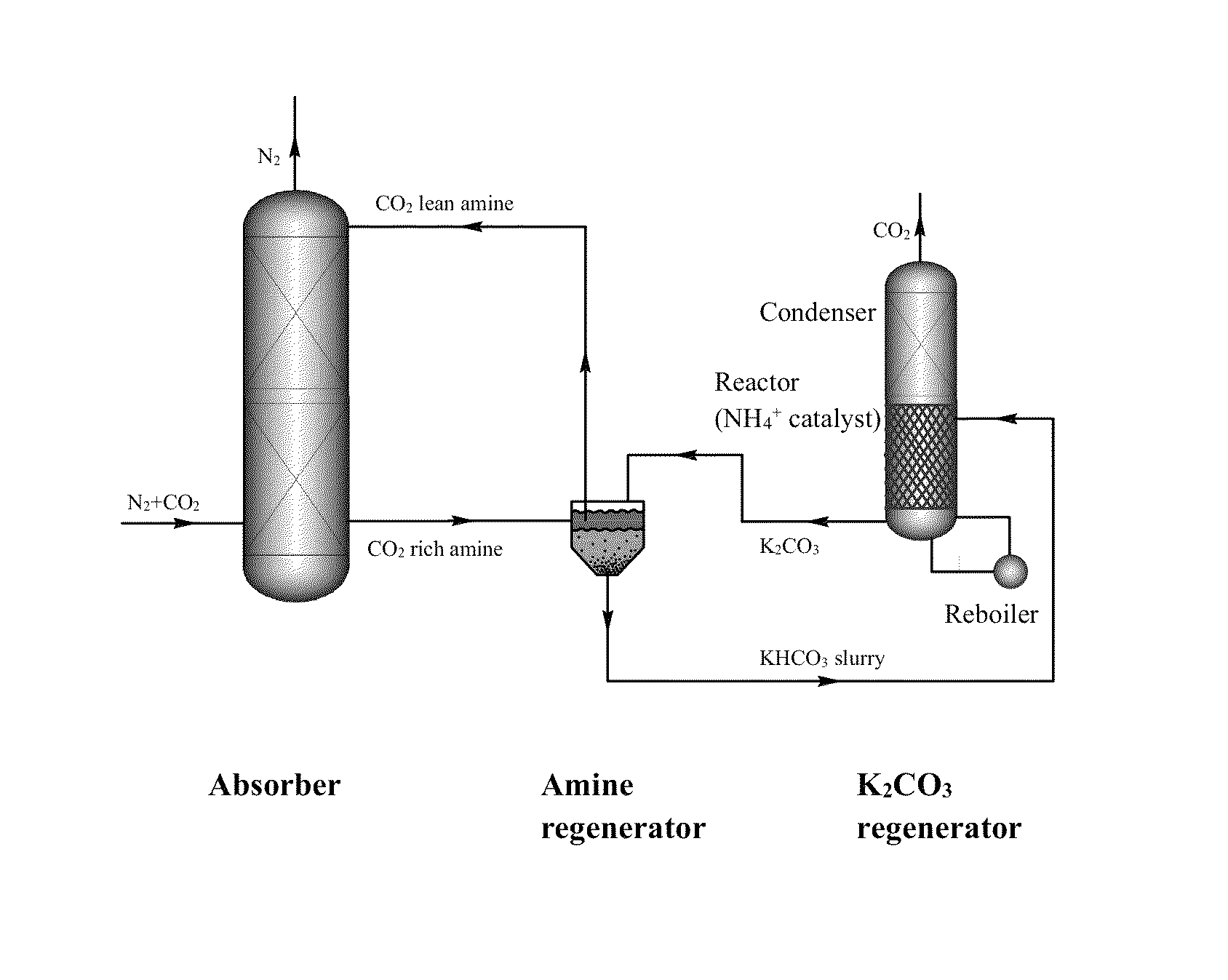
The present invention provides a system for capturing CO2 and / or SO2, comprising: (a) a CO2 and / or SO2 absorber comprising an amine and / or amino acid salt capable of absorbing the CO2 and / or SO2 to produce a CO2- and / or SO2-containing solution; (b) an amine regenerator to regenerate the amine and / or amino acid salt; and, when the system captures CO2, (c) an alkali metal carbonate regenerator comprising an ammonium catalyst capable catalyzing the aqueous alkali metal bicarbonate into the alkali metal carbonate and CO2 gas. The present invention also provides for a system for capturing SO2, comprising: (a) a SO2 absorber comprising aqueous alkali metal carbonate, wherein the alkali metal carbonate is capable of absorbing the SO2 to produce an alkali metal sulfite / sulfate precipitate and CO2.

Description

CROSS-REFERENCE TO RELATED APPLICATIONS[0001]This application is a continuation of International Patent Application No. PCT / US2011 / 049240, filed Aug. 25, 2011 (now International Publication No. WO 2012 / 030630, published Mar. 8, 2012); which claims priority to U.S. Provisional Patent Application Ser. No. 61 / 379,454, filed Sep. 2, 2010; which are incorporated by reference herein in their entirety.STATEMENT OF GOVERNMENTAL SUPPORT[0002]The invention was made with government support under Contract No. DE-AC02-05CH11231 awarded by the U.S. Department of Energy. The government has certain rights in the invention.FIELD OF THE INVENTION[0003]This invention relates generally to emissions abatement processes and to processes that sequester carbon dioxide.BACKGROUND OF THE INVENTION[0004]Greenhouse gases, primarily carbon dioxide are emitted to the atmosphere, causing an effect in which heat reflected from the earth's surface is kept from escaping into space. Thus, there is concern that the at...

Claims


Application Information

Patent Timeline
Patent Type & Authority Patents(United States)
IPC IPC(8): B01D53/14
CPCB01D53/1475B01D53/1406B01D53/1425B01D53/1481B01D53/1493B01D53/501B01D2251/306B01D2251/606B01D2252/10B01D2252/20447B01D2252/20484B01D2252/20489B01D2252/20494B01D2252/602B01D2252/604B01D2252/606B01D2252/608B01D2256/22B01D2257/302B01D2257/504B01D2258/0283Y02C10/06Y02A50/20Y02C20/40
Inventor CHANG, SHIH-GERLI, YANGZHAO, XINGLEI
Owner RGT UNIV OF CALIFORNIA
Learn More