Electric induction heating and stirring of an electrically conductive material in a containment vessel

a technology of electrically conductive materials and containment vessels, which is applied in the direction of inorganic chemistry, crystal growth process, alkali metal halide purification, etc., can solve the problems of local heating and molten metal movement in the pots, insufficient pot insulation alone, and insufficient design of the refractory of the pots

Active Publication Date: 2014-05-27
INDUCTOTHERM INDS
View PDF14 Cites 1 Cited by
  • Summary
  • Abstract
  • Description
  • Claims
  • Application Information

AI Technical Summary

Problems solved by technology

While thermal insulation of the pot itself helps in retaining heat, pot insulation alone is generally insufficient to maintain the molten zinc composition at a desired temperature.
However this results in generally localized heating and molten metal movement in the pots since the coreless electric induction furnaces are stationary and wall mounted relative to the zinc coating material in the pot.
However, one of the disadvantages of a channel furnace is that it complicates the design of the refractory of the pot and adds interfaces between several types of refractory.
Each of these interfaces could be the origin of a leak that can result in electrical shorting and malfunction of the coil.
The pot is taken out of service for an extended period of time while the costly refurbishing process is accomplished.
Channel inductors are also used in zinc or copper (cathode or anode) melters (or smelters) for heating and stirring a metal composition where zinc or copper is extracted from ore or scrap by an electrolysis (or electrolytic) process, and are subject to limitations in this process similar to those described above for a coating process.
However a flux residue accumulates in the region and interferes with the workpiece coating process.

Method used


Image

  • Electric induction heating and stirring of an electrically conductive material in a containment vessel
  • Electric induction heating and stirring of an electrically conductive material in a containment vessel
  • Electric induction heating and stirring of an electrically conductive material in a containment vessel

Examples


Embodiment Construction

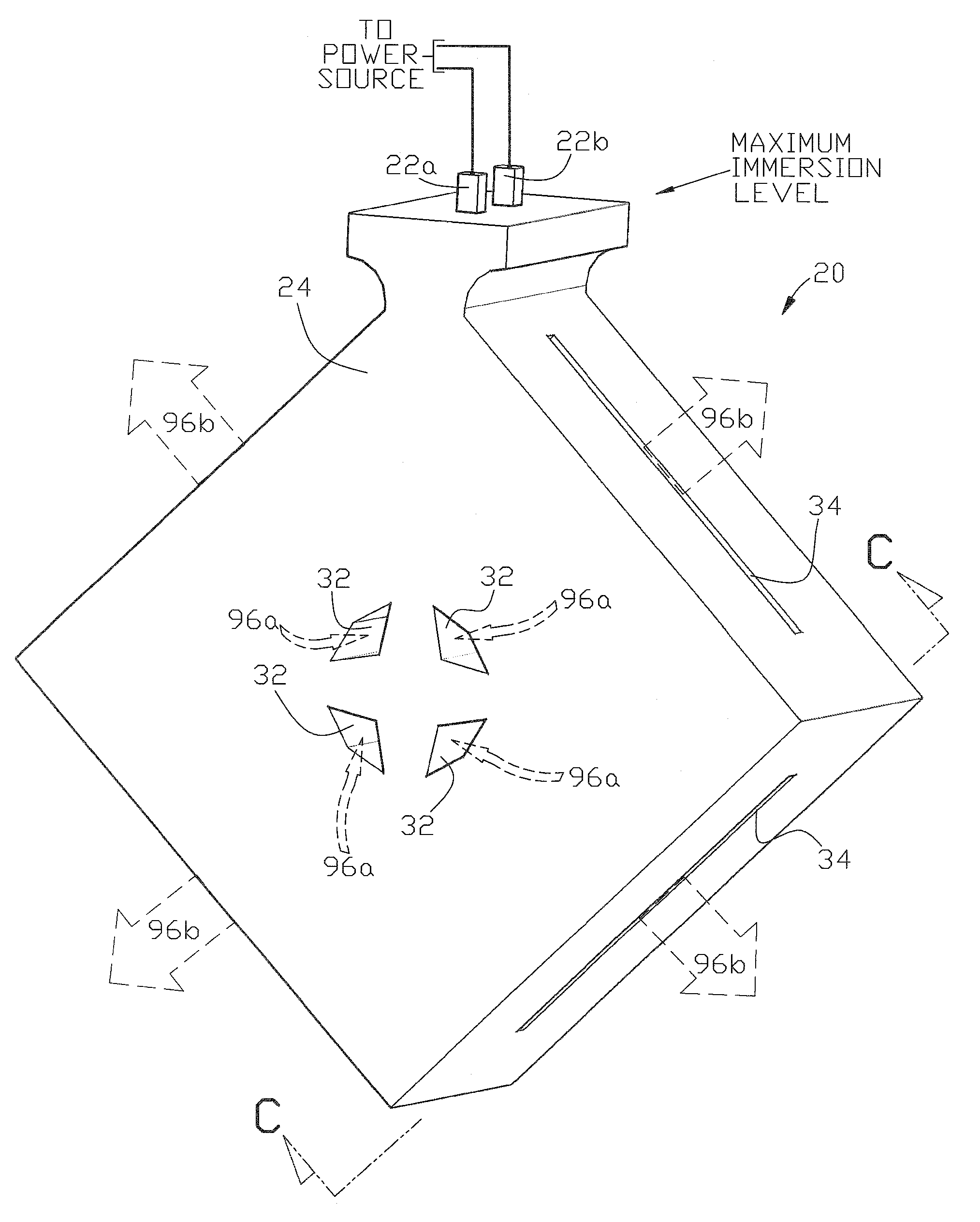
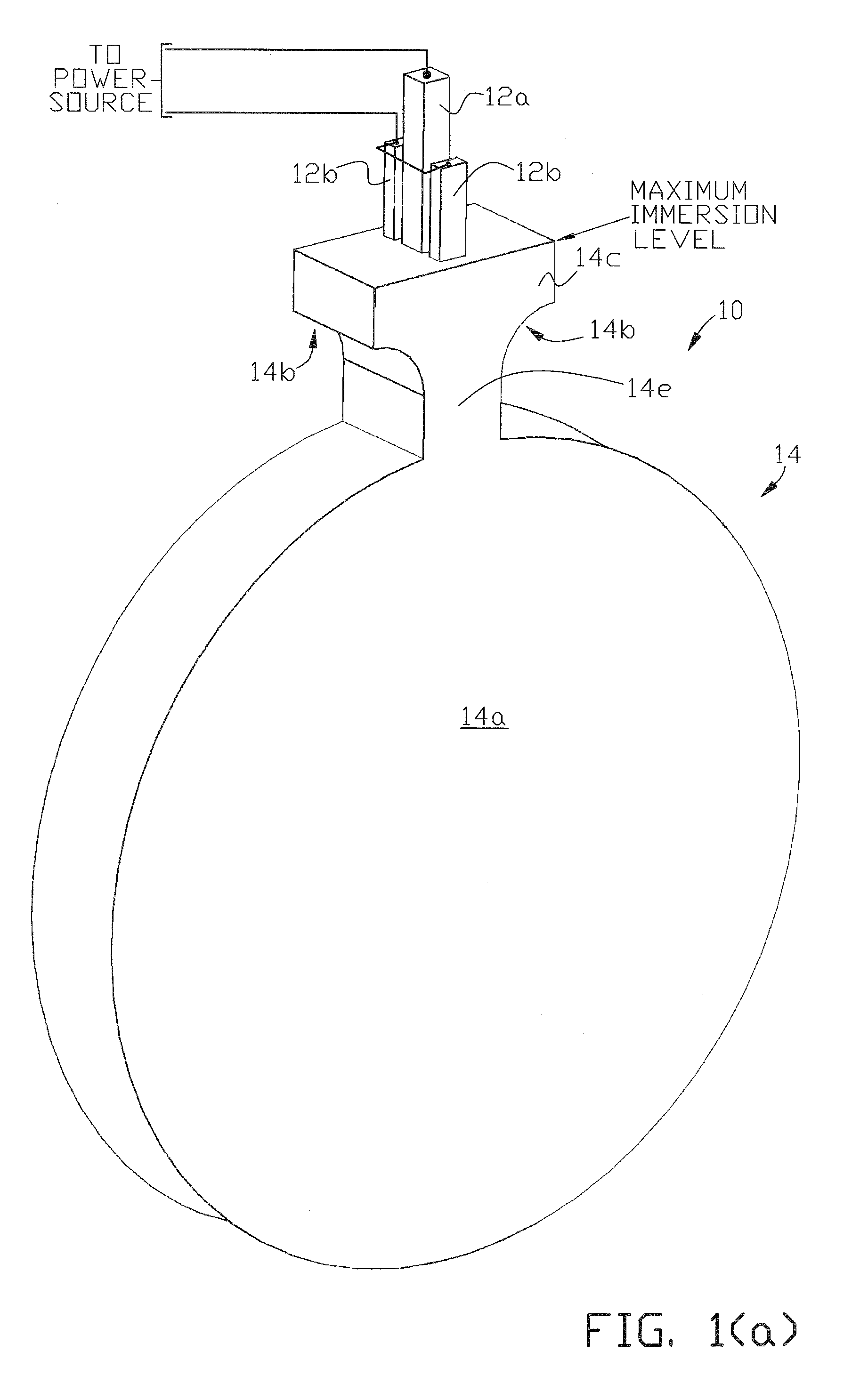
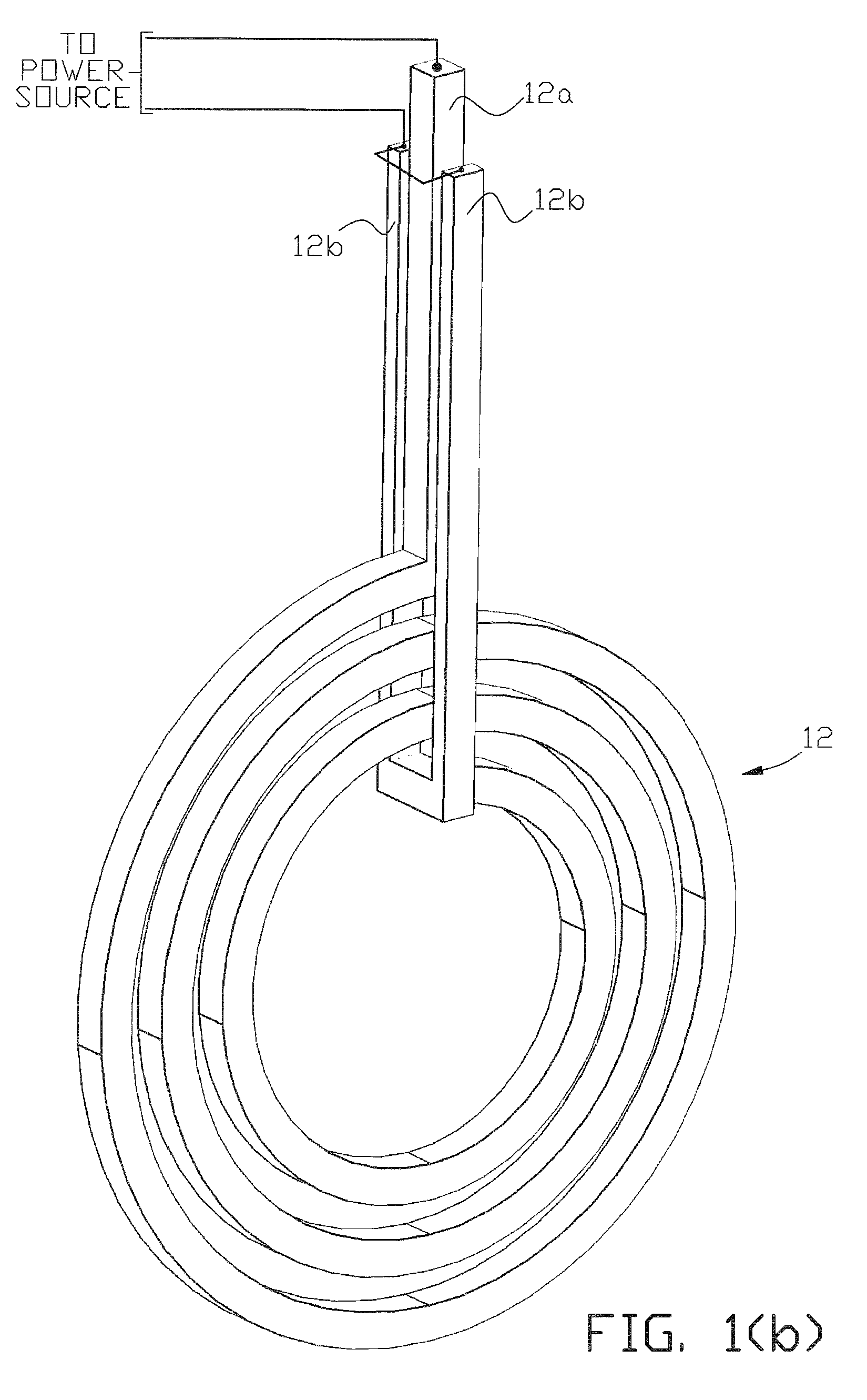
[0039]FIG. 1(a), FIG. 1(b), FIG. 1(c) and FIG. 1(d) illustrate one example of a submersible electric induction heating and stirring apparatus 10 of the present invention. In use, apparatus 10 is removably inserted in a container, such as a holding vessel, coating pot, or anode or cathode melter, holding molten metal or another electrically conductive material or composition. Induction coil 12 (FIG. 1(b)) is embedded within refractory 14 (FIG. 1(a)). Although the refractory is shown in the shape of a solid exterior disc in FIG. 1(a), any suitable configuration of refractory (that is, any abrasive and heat resistant media) may be used as long as it isolates the embedded coil from the surrounding molten metal. For example the refractory may be shaped in a rectangular or diamond. A suitable refractory or coating material can be selected based upon the type of molten metal in the vessel. For example, if the molten metal is silicon, at least the outer surface of the refractory may be of a...


PUM

PropertyMeasurementUnit
electrically conductiveaaaaaaaaaa
electrically interconnectedaaaaaaaaaa
electric poweraaaaaaaaaa

Abstract

Apparatus and method are provided for electric induction heating and / or stirring of a molten electrically conductive composition in a containment vessel with the apparatus being removably insertable in the molten composition. An induction coil embedded in refractory or a coating is submerged in the composition and used to heat and / or stir the molten composition either externally or internally to the refractory or coating.

Description

CROSS REFERENCE TO RELATED APPLICATIONS[0001]This application claims the benefit of U.S. Provisional Application No. 61 / 218,964, filed Jun. 21, 2009, which is hereby incorporated by reference in its entirety.FIELD OF THE INVENTION[0002]The present invention relates generally to electric induction heating or stirring of an electrically conductive material in a containment vessel, and in particular, to such heating or stirring when accomplished with an electric inductor assembly that can be removably inserted in the containment vessel.BACKGROUND OF THE INVENTION[0003]Containers for holding hot electrically conductive materials over an extended period of time at temperatures above liquidus are used in various industrial applications. For example a steel workpiece or article can be dipped into a container holding a hot molten zinc composition to zinc-coat the article in a galvanizing process. The container is generally referred to as a coating pot. The steel workpiece or article dipped ...

Claims


Application Information

Patent Timeline
Patent Type & Authority Patents(United States)
IPC IPC(8): H05B6/34B23K13/01H05B6/36H05B6/22
CPCH05B6/34H05B6/36H05B6/42H05B2213/02H05B6/44H05B6/24F27B14/065F27D11/06F27D27/00F27D2099/0015H05B6/367Y02P10/25
Inventor LOVENS, JEANFONTAINE, MICHELRAFFNER, BERNARD M.
Owner INDUCTOTHERM INDS
Why Eureka
Try Eureka