
Implantable medical device and method for detecting cardiac events without using of refractory or blanking periods

a medical device and implantable technology, applied in the field of implantable medical devices, can solve the problems of device failure to detect a bradycardia, atria subject to a tachyarrhythmia, device malfunction,

Inactive Publication Date: 2005-08-02
PACESETTER INC
View PDF13 Cites 69 Cited by
  • Summary
  • Abstract
  • Description
  • Claims
  • Application Information

AI Technical Summary

Benefits of technology

[0017]For example, the device programmer takes all signal vectors identified as being P-waves, based on the ECG, and determines the geometric range for the P-wave classification zone based on the P-wave signal vectors. In this regard, the device programmer determines the P-wave direction vector, the maximum angle relative to the P-wave direction vector, the minimum P-wave vector length and the maximum P-wave vector length. The P-wave direction vector is determined by averaging the directions of all of the individual P-wave vectors. The maximum angle relative to the P-wave direction vector is determined by finding the individual P-wave having the gr

Problems solved by technology

As a result, any functions performed by the pacemaker, which require accurate detection of P-waves, may not function as intended.
For example, the calculated atrial rate will be higher than the actual atrial rate, perhaps causing the device to erroneously conclude that the atria are subject to a tachyarrhythmia, which does not in fact exist.
Alternatively, the overestimated atrial heart rate may cause the device to fail to detect a bradycardia, which does exist.
As a result, inappropriate therapy may be administered.
For an ICD, an erroneously high determination of the atrial rate may cause the ICD to incorrectly conclude that the heart is subject to atrial fibrillation, resulting in a potentially painful cardioversion pulse administered to the atrium.
This requires a careful and time-consuming review by the physician of programming parameters used to set the refractory and blanking periods within the implanted device and may necessitate several follow-up sessions between patient and physician before the parameters are set properly.
Also, the discrimination algorithm employed by the implanted device is quite complicated and prone to event misidentification.
One example of a problem that can arise when using refractory and blanking periods involves the misidentification of far field R-waves as P-waves.
In any event, if the far field R-wave is detected within the atria without an immediately preceding R-wave detection in the ventricles, the aforementioned PVAB interval is ineffective to filter out the far field R-wave from the atrial IEGM.
As a result, far field R-waves are misclassified as P-waves resulting in incorrect determination of atrial rate, or other critical parameters, causing potentially erroneous therapy to be administered by the pacemaker.
Another example of a problem that can arise when using refractory and blanking periods involves the miscalculation of high atrial rates when using Combipolar sensing.
Accordingly, the use of conventional blanking and refractory periods in connection with Combipolar sensing can result in T-waves being misidentified as P-waves, thereby yielding an incorrect atrial rate, particularly at high atrial rates.

Method used


Image

  • Implantable medical device and method for detecting cardiac events without using of refractory or blanking periods
  • Implantable medical device and method for detecting cardiac events without using of refractory or blanking periods
  • Implantable medical device and method for detecting cardiac events without using of refractory or blanking periods

Examples


Embodiment Construction

[0031]The following description includes the best mode presently contemplated for practicing the invention. The description is not to be taken in a limiting sense but is made merely for the purpose of describing the general principles of the invention. The scope of the invention should be ascertained with reference to the issued claims. In the description of the invention that follows, like numerals or reference designators will be used to refer to like parts or elements throughout.

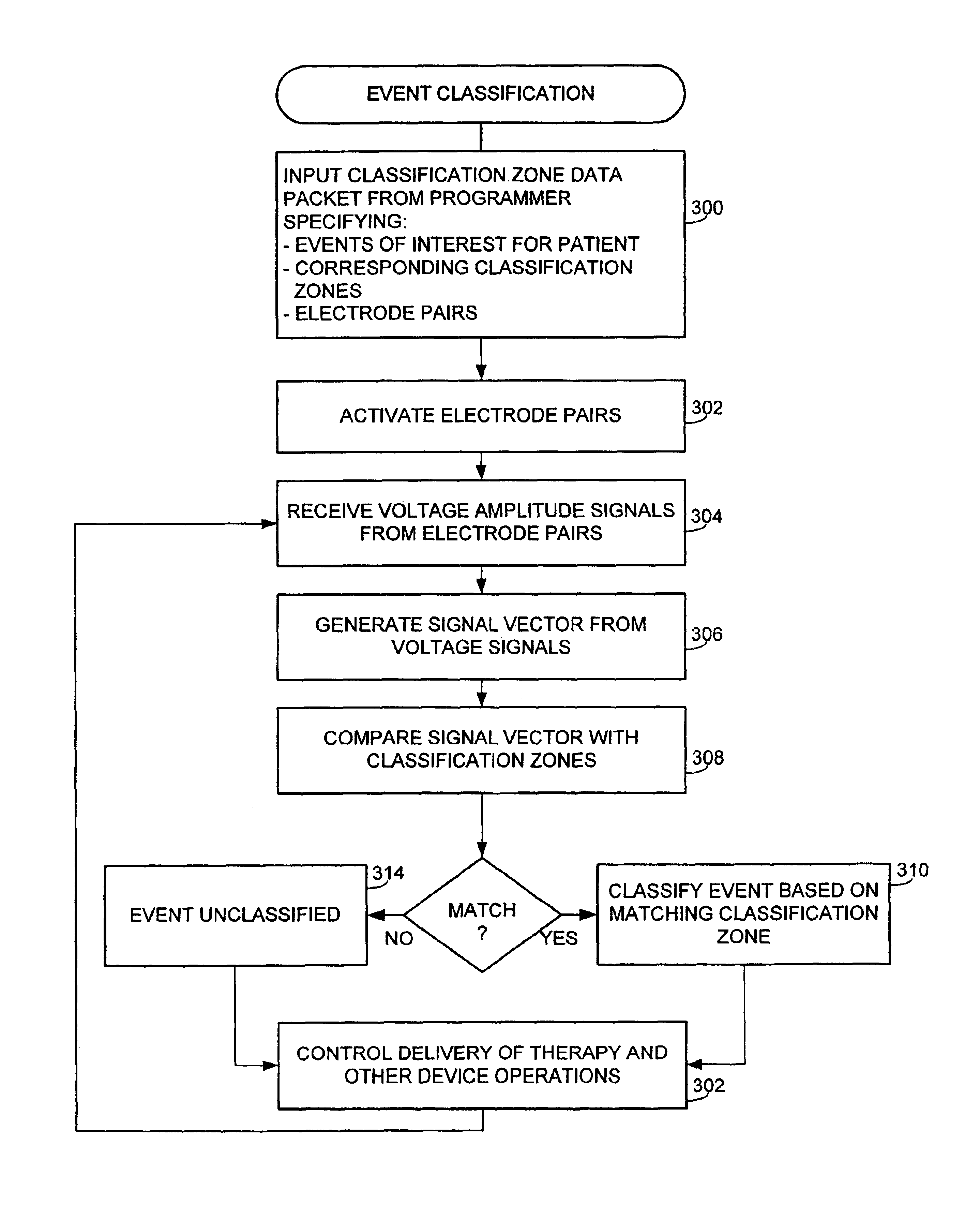
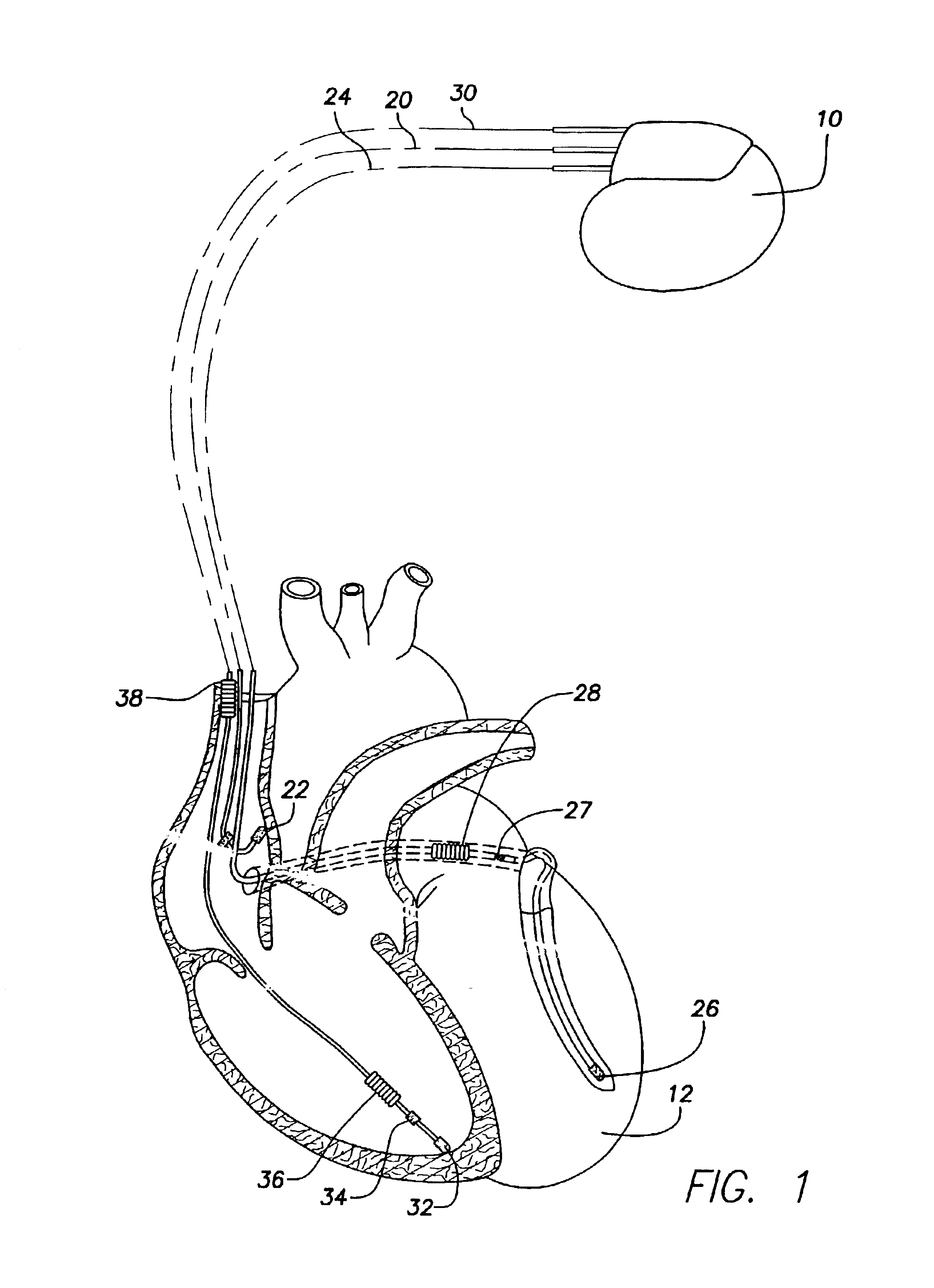
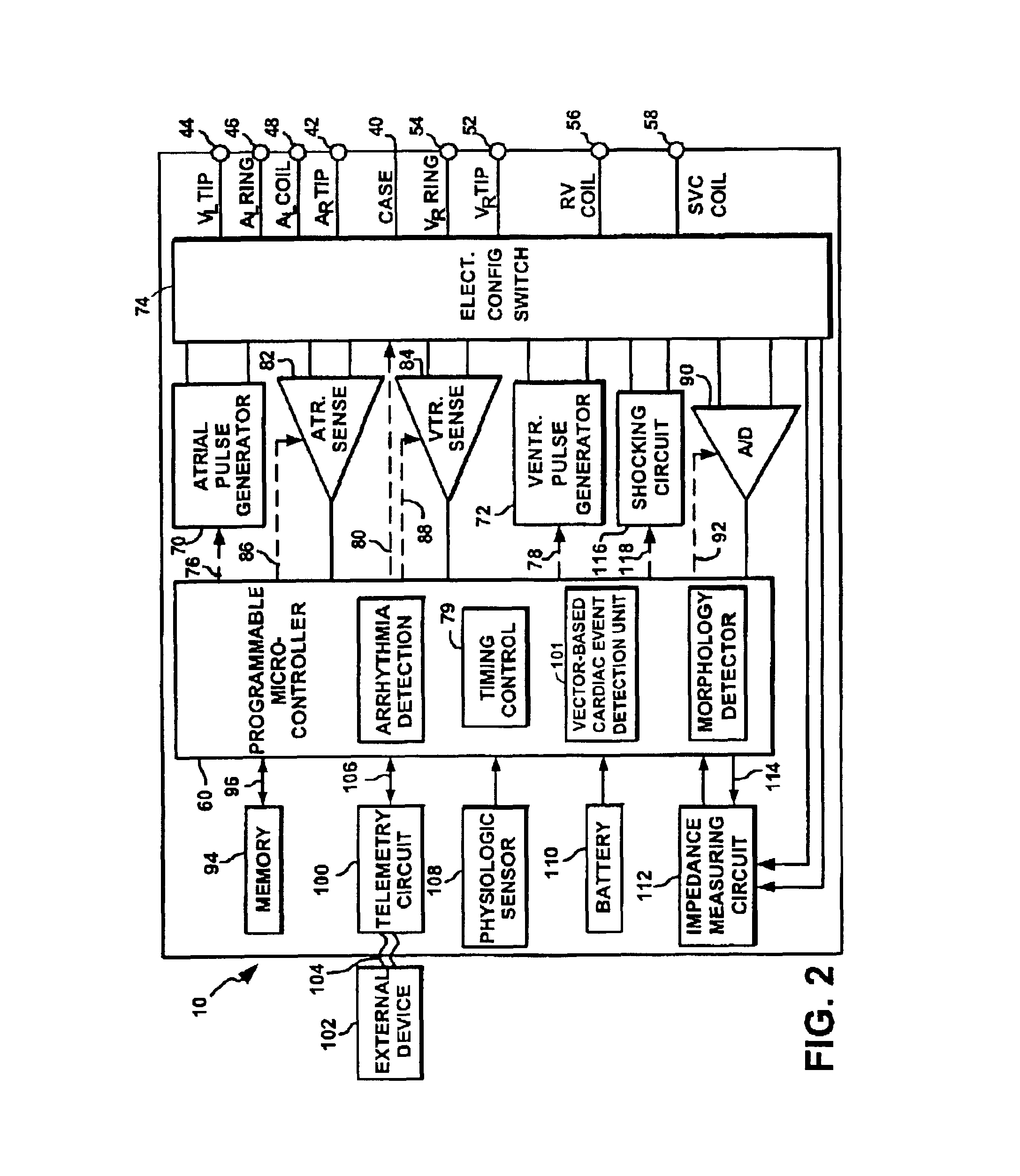
[0032]Exemplary systems and methods using signal vectors are described for classifying electrical events, such P-waves, R-waves, etc., sensed within the heart of a patient. The classification method is performed by an implantable cardiac stimulation service subject to programming commands received from an external programmer. Initially, an overview of the implanted device is provided with reference to FIGS. 1 and 2 and an overview of an external programmer used to program the device is then provided with ...


PUM


Abstract

Cardiac electrical events are detected by comparing signal vectors with pre-determined classification zones representative of different cardiac events. The signal vector is generated by sensing the voltages between various combinations of electrodes, such as A-tip to V-tip, A-tip to A-ring, and A-ring to V-ring. The signal vector is compared with a set of classification zones corresponding to different events, such as P-waves, R-waves, T-waves, A-pulses, and V-pulses, to determine whether the vector lies within any of the classification zones. In this manner, cardiac events are detected using only the voltages received from the electrodes and no refractory periods or blanking periods are required to distinguish one event from another. The classification zones vary from patient to patient and a technique is provided herein for generating a set of vector classification zones for a particular patient. Signal vectors corresponding to various unknown cardiac events are generated by the implanted device and are transmitted to an external device programmer. ECG signals, generated by a surface ECG detector, are simultaneously received by the external programmer. The external programmer identifies the cardiac electrical event corresponding to each signal vector based on the ECG signals and then generates classification zones for each event type using only the signal vectors corresponding to the event.

Description

CROSS-REFERENCE TO RELATED APPLICATIONS[0001]This application is related to copending U.S. patent application Ser. No. 10 / 139,042, titled “IMPLANTABLE MEDICAL DEVICE AND METHOD FOR DETECTING CARDIAC EVENTS WITHOUT USING OF REFRACTORY OR BLANKING PERIODS,” filed concurrently herewith.FIELD OF THE INVENTION[0002]The invention generally relates to implantable medical devices, such as pacemakers or implantable cardioverter-defibrillators (“ICDs”) and, in particular, to techniques for detecting electrical cardiac events using an implantable medical device.BACKGROUND OF THE INVENTION[0003]A pacemaker is a medical device, typically implanted within a patient, which recognizes various disrythmias such as an abnormally slow heart rate (bradycardia) or an abnormally fast heart rate (tachycardia) and delivers electrical pacing pulses to the heart in an effort to remedy the disrythmias. An ICD is a device, also implantable into a patient, which additionally recognizes atrial fibrillation (AF) o...

Claims


Application Information

Patent Timeline
IPC IPC(8): A61N1/368A61N1/362
CPCA61N1/3622A61N1/368
Inventor KLEINE, BRUCE
Owner PACESETTER INC
Learn More