
Spark plug having stress corrosion cracking resistance

a stress corrosion cracking and spark plug technology, applied in spark plugs, basic electric elements, electric devices, etc., can solve the problems of stress corrosion cracking in the stress corrosion cracking portion, large residual stress generation in the stress corrosion portion, and high hardness, so as to reduce environmental burden and improve corrosion resistance

Active Publication Date: 2014-05-06
NGK SPARK PLUG CO LTD
View PDF12 Cites 2 Cited by
  • Summary
  • Abstract
  • Description
  • Claims
  • Application Information

AI Technical Summary

Benefits of technology

[0009]According to the above-mentioned conventional technique (See Japanese Patent Application Laid-Open (kokai) No. 2002-184552), an electrolytic chromating process is performed such that 95% by mass or more of the chromium component of a chromate layer is trivalent chromium. The purpose of such chromating is to reduce environmental burden through attainment of substantially zero content of hexavalent chromium and to improve corrosion resistance against salt water (salt corrosion resistance).
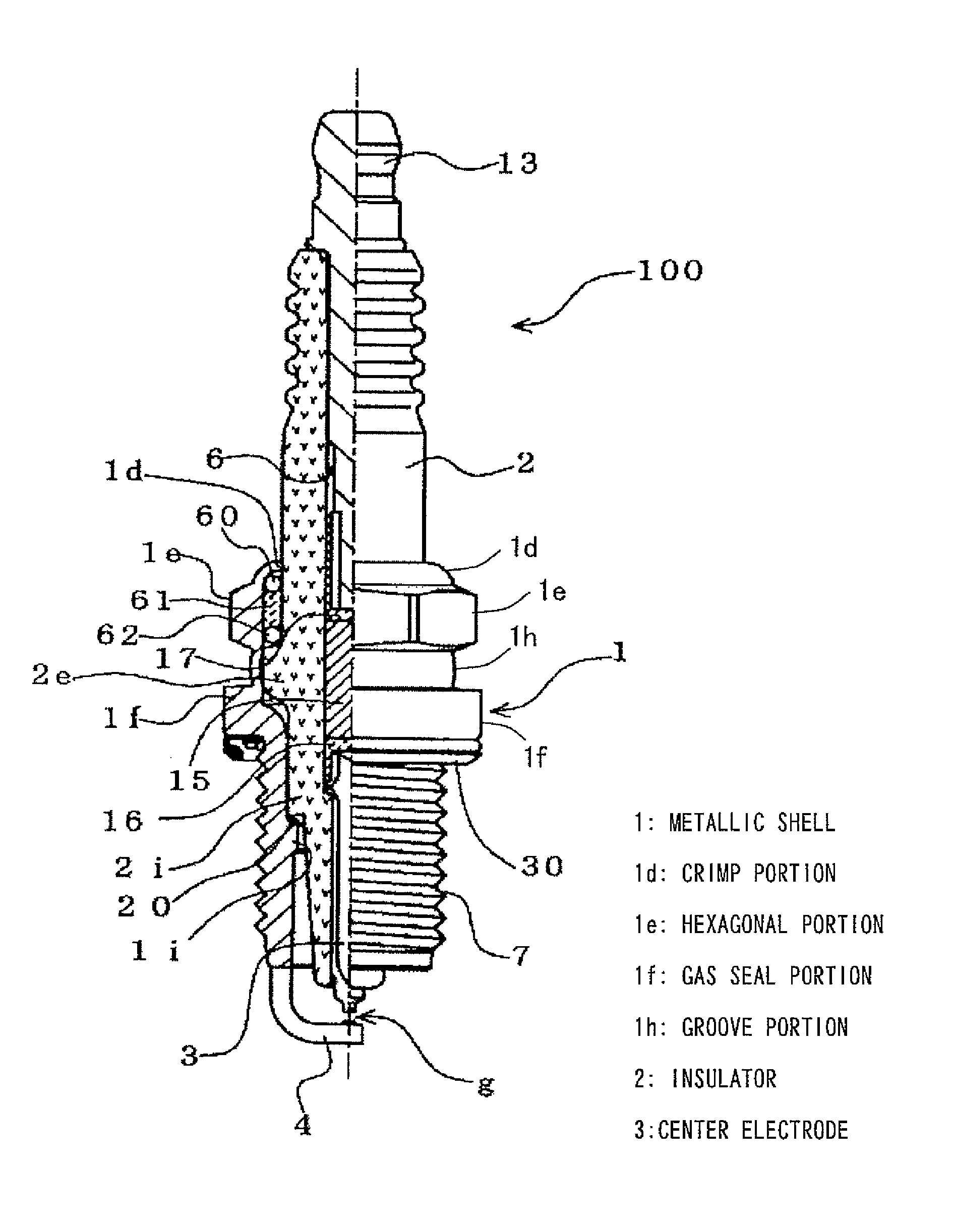
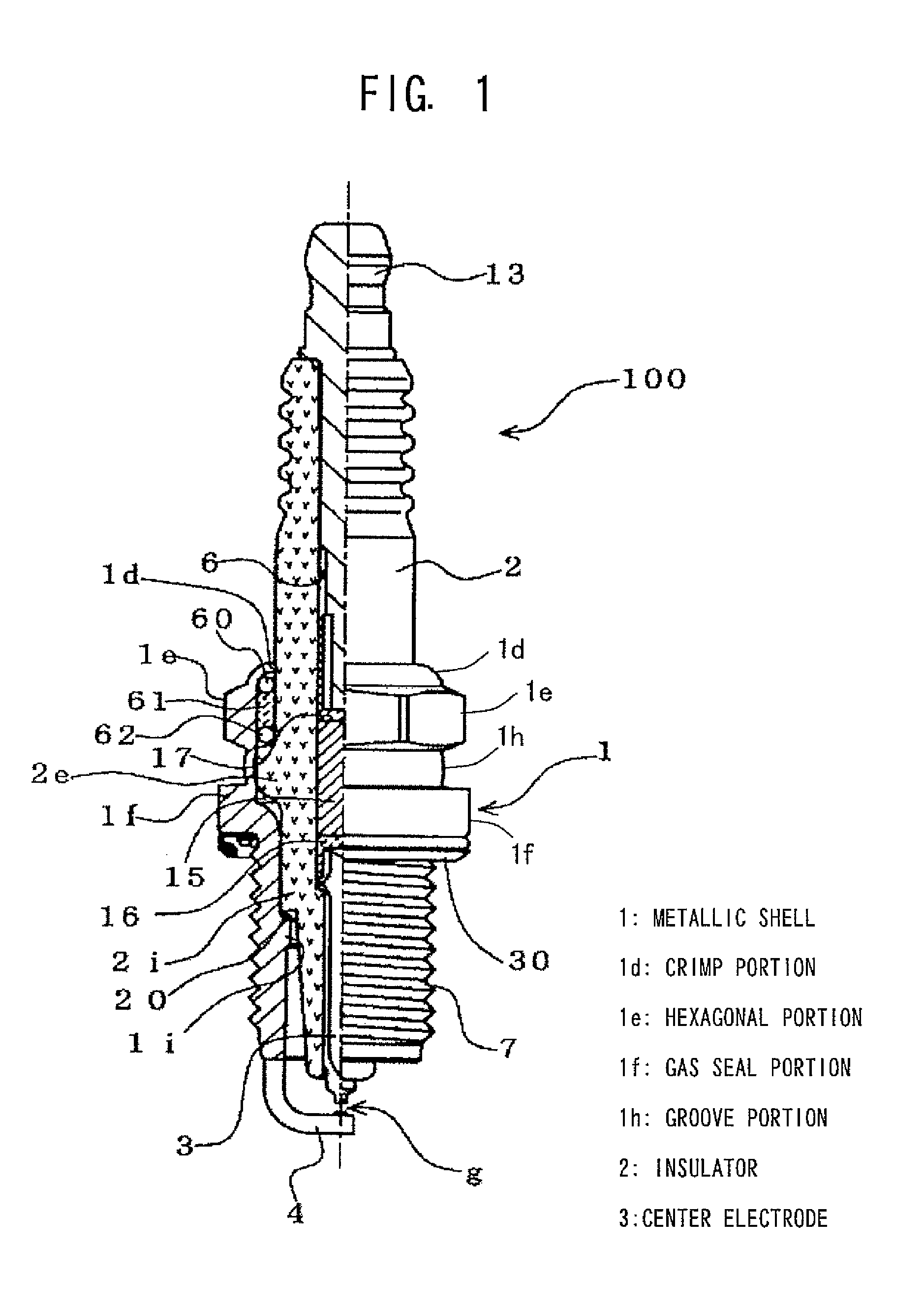
[0013]An object of the present invention is to provide a spark plug to which excellent stress corrosion cracking resistance is imparted by means of appropriately specifying the nickel plating thickness of the inner surface of the metallic shell.
[0063]The configuration of application example 2 can provide a spark plug having excellent stress corrosion cracking resistance in the case where the chromium-containing layer is formed on the nickel plating layer of the metallic shell, by means of employing a nickel plating layer thickness of 0.2 μm to 2.2 μm as measured at the forward end of the inner circumferential surface of the groove portion of the metallic shell.
[0064]The configuration of application example 3 can provide a spark plug having excellent stress corrosion cracking resistance in the case where rust prevention oil is applied onto the nickel plating layer of the metallic shell, by means of employing a nickel plating layer thickness of 0.2 μm to 2.2 μm as measured at the forward end of the inner circumferential surface of the groove portion of the metallic shell.
[0065]The configuration of application example 4 can provide a spark plug having excellent stress corrosion cracking resistance in the case where the chromium-containing layer is formed on the nickel plating layer of the metallic shell, and rust prevention oil is applied onto the chromium-containing layer, by means of employing a nickel plating layer thickness of 0.1 μm to 2.4 μm as measured at the forward end of the inner circumferential surface of the groove portion of the metallic shell.
[0066]The configuration of application example 5 can provide a spark plug having not only excellent stress corrosion cracking resistance but also excellent corrosion resistance (salt corrosion resistance) and plating peeling resistance.

Problems solved by technology

However, as mentioned above, crimping causes the crimp portion 1d and the groove portion 1h to be greatly deformed, resulting in the generation of a large residual stress in these portions; therefore, corrosion resistance is a big problem for these portions.
A portion which has such high hardness and in which a large residual stress exists may suffer stress corrosion cracking.
Such a problem to consider is also marked in the case of employing hot crimping.
Conventionally employed nickel plating specifications give importance to corrosion resistance of the outer surface of the metallic shell and tend to not give much importance to the plating thickness of the inner surface.
However, since the inner surface of the metallic shell is in a closed space, dew condensation is apt to occur thereon upon exposure to coldness.
Also, since the inner surface is thin in plating thickness as compared with the outer surface, the occurrence of stress corrosion cracking associated with progress of corrosion is more concerned.
However, in actuality, the following has been found: when plating on the inner surface is excessively thick, crimping-induced deformation causes cracking to occur in the plating on the inner surface, resulting in deterioration in stress corrosion cracking resistance.

Method used


Image

  • Spark plug having stress corrosion cracking resistance
  • Spark plug having stress corrosion cracking resistance
  • Spark plug having stress corrosion cracking resistance

Examples


examples

(1) First Example (Ni Strike Plating+Ni Plating)

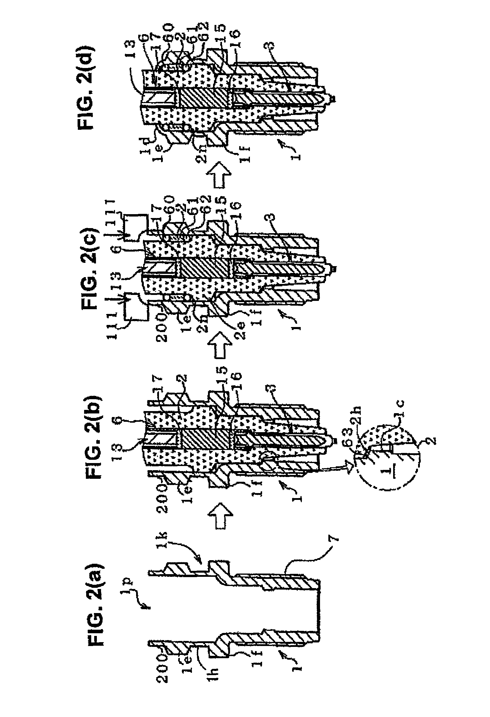
[0117]In the first example, there were manufactured a plurality of metallic shell samples which differed in the Ni plating thickness of the inner surface by executing step T100 (Ni strike plating process) and step T110 (electrolytic Ni plating process) of FIG. 3 while omitting step S120 (electrolytic chromating process) and step T130 (application of rust prevention oil) of FIG. 3. These metallic shells were subjected to a stress corrosion cracking resistance evaluation test.

[0118]First, the metallic shells 1 were manufactured, by cold forging, from a carbon steel wire SWCH17K for cold forging specified in JIS G3539. The ground electrodes 4 were welded to the respective metallic shells 1, followed by degreasing and water washing. Subsequently, a nickel strike plating process was performed under the following processing conditions by use of a rotary barrel.

[0119]Processing Conditions of Nickel Strike Plating

[0120]Composition of plating b...


PUM


Abstract

A spark plug having a metallic shell covered with a nickel plating layer and having a groove portion formed between a tool engagement portion and a gas seal portion and having an orthogonal-to-axis sectional area of 36 mm2 or less.

Description

FIELD OF THE INVENTION[0001]The present invention relates to a spark plug for an internal combustion engine.BACKGROUND OF THE INVENTION[0002]A spark plug for providing ignition in an internal combustion engine, such as a gasoline engine, has the following structure: an insulator is provided externally of a center electrode; a metallic shell is provided externally of the insulator; and a ground electrode which forms a spark discharge gap in cooperation with the center electrode is attached to the metallic shell. The metallic shell is generally formed from an iron-based material, such as carbon steel, and, in many cases, plating is performed on its surface for corrosion protection. A known technique associated with such a plating layer employs a 2-layer structure consisting of an Ni plating layer and a chromate layer (See Japanese Patent Application Laid-Open (kokai) No. 2002-184552). However, the inventors of the present invention have found that, even in employment of a plating laye...

Claims


Application Information

Patent Timeline
Patent Type & Authority Patents(United States)
IPC IPC(8): H01T13/39
CPCH01T13/36H01T13/20H01T13/39H01T13/02
Inventor NASU, HIROAKISUGITA, MAKOTOSATO, AKITOKUWAHARA, SHINGO
Owner NGK SPARK PLUG CO LTD
Learn More