Process for roughening metal surfaces

a metal surface and roughening technology, applied in the direction of metal-working feeding devices, forging/pressing/hammering apparatuses, handling devices, etc., can solve the problems of plastic deformation of ridges over their entire length, requires a relatively large effort, and the shape of undercuts is constant only with difficulty, so as to achieve the effect of reducing the amount of undercuts and ensuring the effect of smoothness

Inactive Publication Date: 2014-04-29
FORD GLOBAL TECH LLC
View PDF45 Cites 7 Cited by
  • Summary
  • Abstract
  • Description
  • Claims
  • Application Information

AI Technical Summary

Benefits of technology

[0007]This regular variation in the groove shape means that the undercuts which then occur regularly can be introduced into the ridges with relatively little effort since, overall, only a small degree of plastic deformation of the ridges is required. Furthermore, the undercuts can be introduced with increased accuracy. As a result, these are produced regularly with identical dimensions along the grooves. This is a major advantage for uniform adhesive strength of the sprayed layer subsequently applied. It is also advantageous that the spraying material to be applied can fill the grooves very well since these regularly do not have any undercuts or have at least relatively small undercuts. In these regions, the spraying material penetrates very well into each groove and can then easily fill the directly adjacent groove regions with the undercuts.
[0014]A tool for introducing the plastic deformations may be guided in, on, or by a groove. Therefore, it is possible for the tool to always be aligned precisely with respect to the ridges and for only one of the adjacent ridges to be machined. Since the tool is guided on, by, or in the grooves, the ridges are always deformed relative to the groove and the deformation can thus be carried out with high precision and repeatability.
[0015]It is particularly advantageous if the plastic deformations in the second process step are introduced in the same operation as the first process step. By way of example, a tool for the plastic deformation can be arranged downstream of a turning, drilling or milling tool. In this case, the tools for the first and second process steps are advantageously mounted on the same tool carrier, e.g. a milling or turning spindle. Therefore, the first and second process steps take place virtually at the same time or in brief succession. In addition to reduced time (no further operation is necessary), the outlay in terms of measurement or apparatus is also reduced for the second process step. Both tools are coupled directly to each other and have to be aligned with respect to each another only once.
[0017]The disclosed method is particularly suitable for machining and preparing the coating of cylinder blocks of internal combustion engines. The process is readily useable in the relatively small cylinder bore since it is possible to reliably introduce the undercuts required into the ridges in a very uniform manner with little effort.

Problems solved by technology

A disadvantage of this process is that the ridges are plastically deformed over their entire length.
This requires a relatively large effort, it being possible to make the shape of the undercuts constant only with difficulty.
Furthermore, the formation of the undercuts over the entire length of the grooves ensures that the grooves are filled completely by the spraying material only to a limited extent, since the adjacent undercuts form a narrow point through which only some of the spraying material can penetrate into a groove.

Method used


Image

  • Process for roughening metal surfaces
  • Process for roughening metal surfaces
  • Process for roughening metal surfaces

Examples


Embodiment Construction

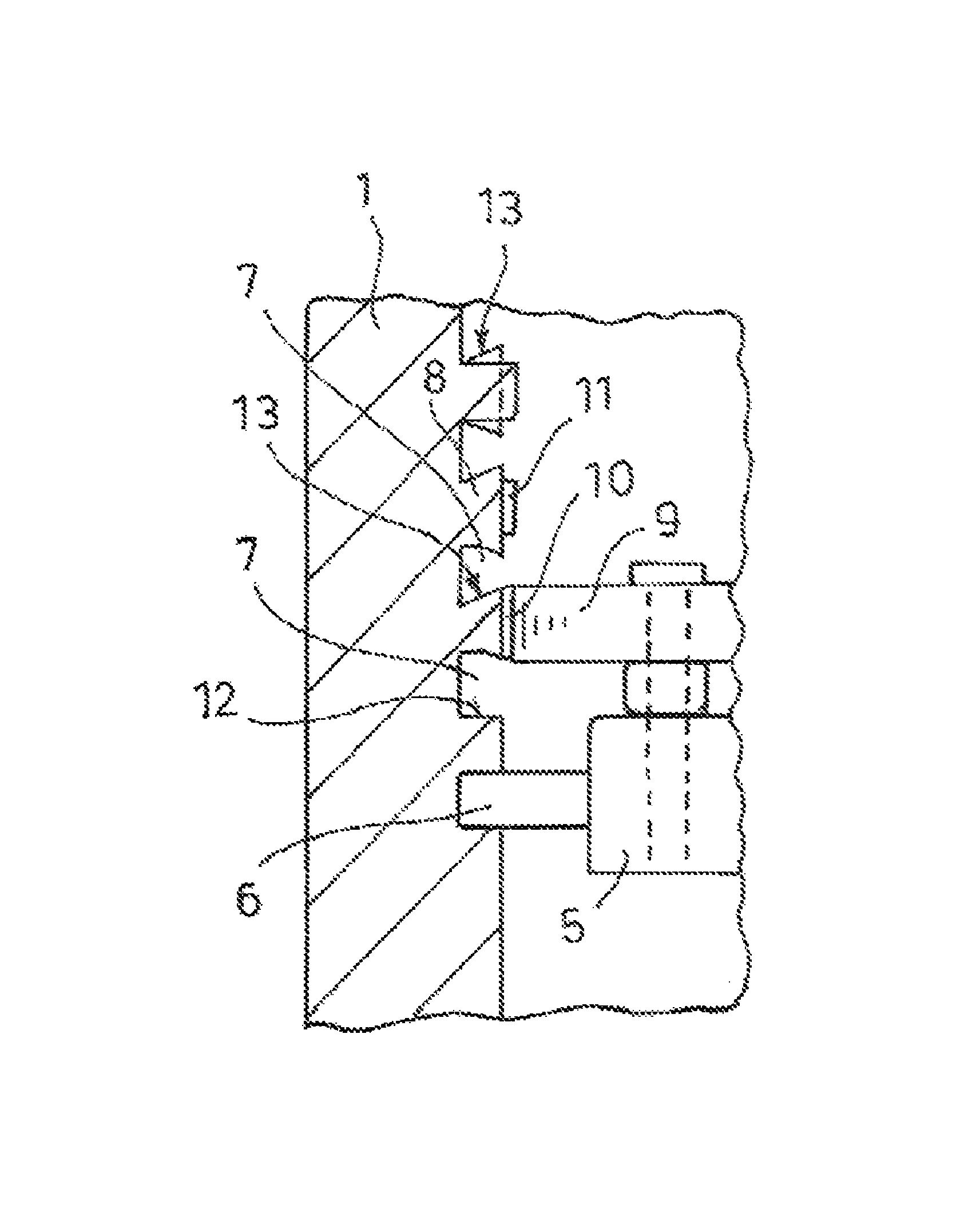
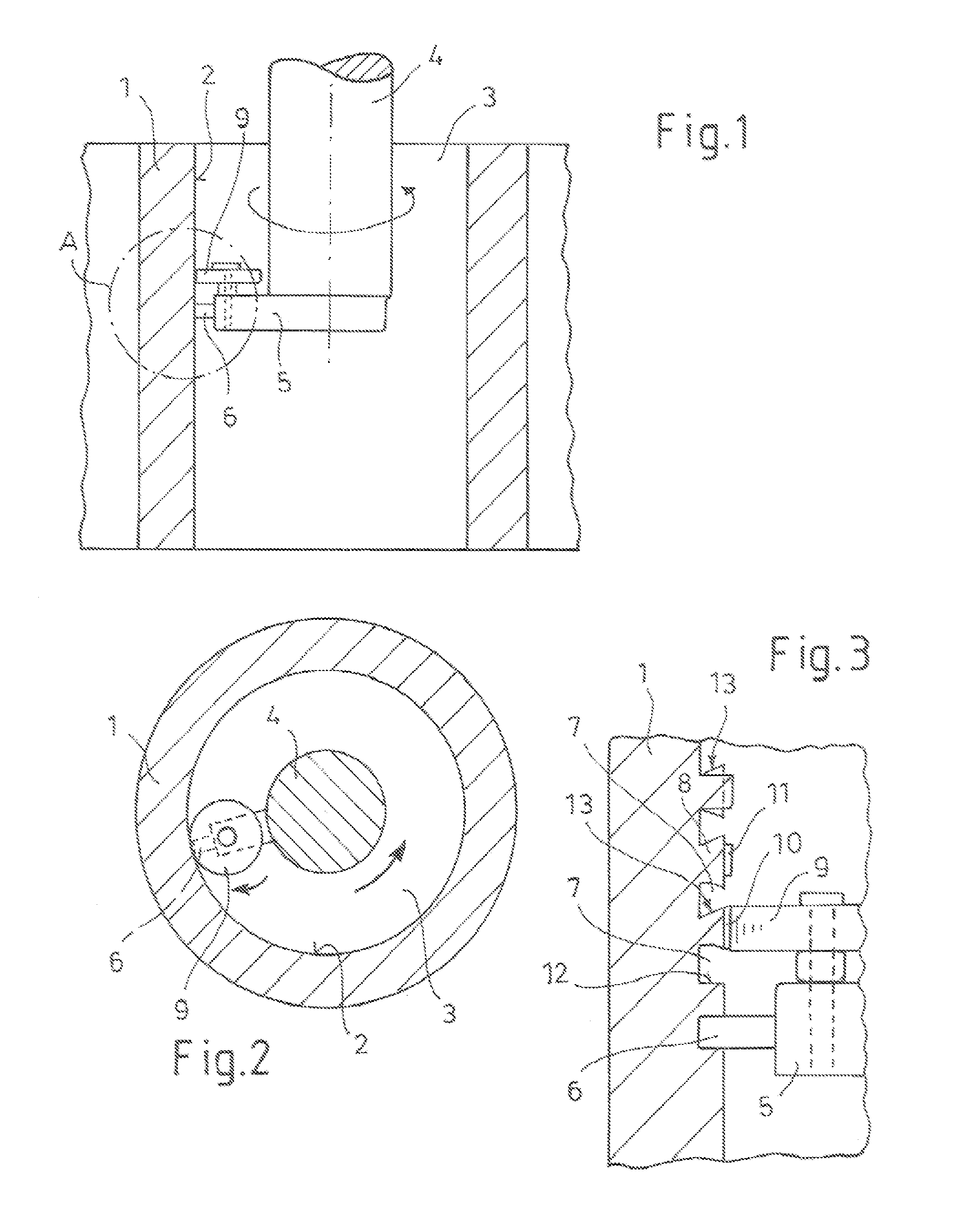
[0030]FIGS. 1 to 3 show an arrangement for carrying out a surface roughening. The workpiece may be, for example, a cylinder block 1 and has a metal surface 2 which is prepared by means of the process in order to make it possible to apply a sprayed layer. A tool holder 5, which bears a turning tool 6, is fastened to a tool spindle 4. Since the tool spindle 4 rotates and slowly moves downward into the cylinder bore 3, the turning tool 6 produces, in the metal surface 2, the grooves 7 which run in the circumferential direction and have the intermediate ridges 8.

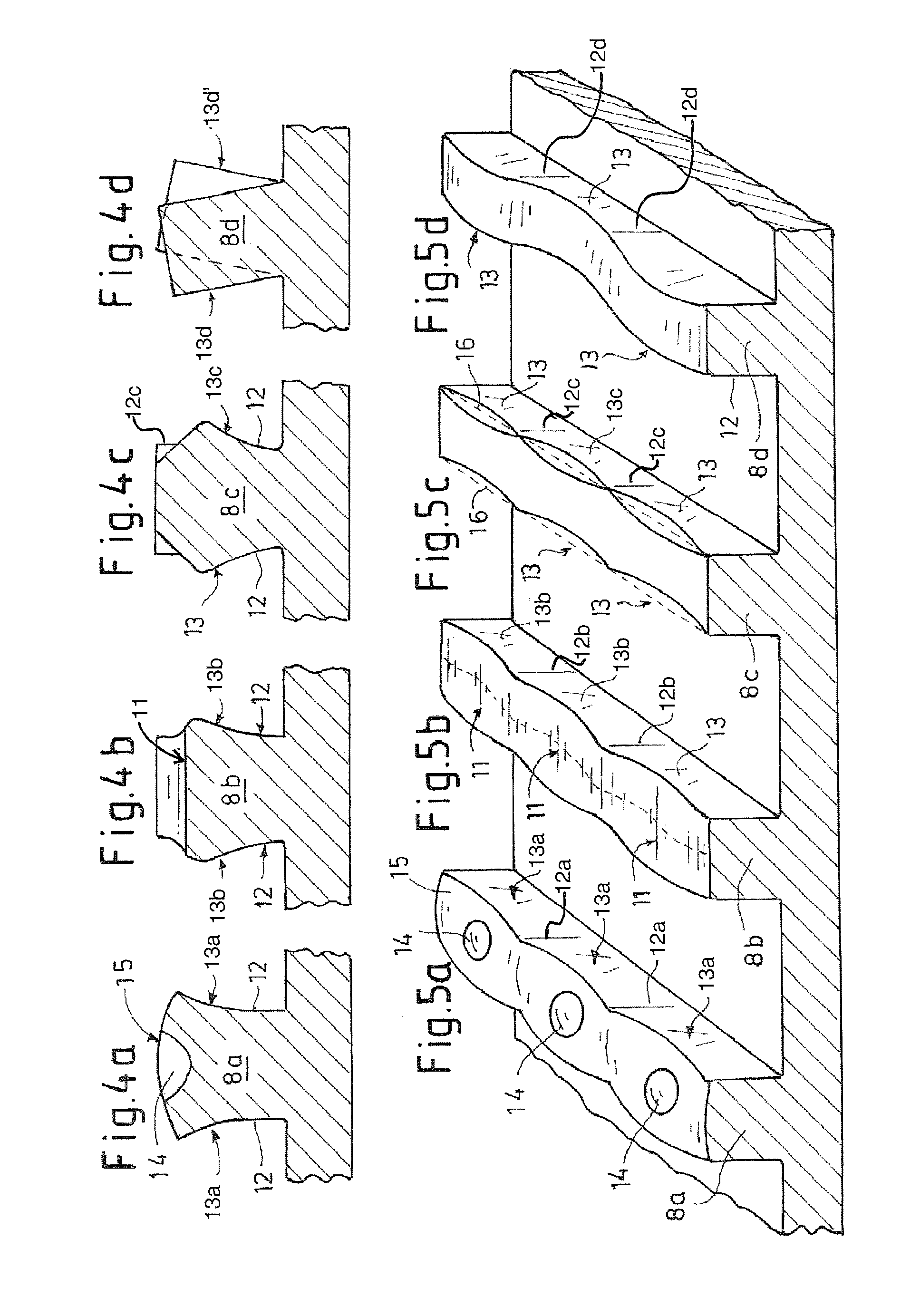
[0031]A rotatable knurling roller 9 is arranged on the tool holder 5 and acts on the ridges 8 by means of regular projections 10 which are arranged on the circumference and, when the rotary spindle 4 rotates, plastically deform the ridges 8 at regular intervals in the form of knurls or flutes 11. These flutes 11 in turn produce the undercuts 13 on the groove flanks 12 of the ridges 8.

[0032]The knurling roller 9 is set back axial...


PUM

PropertyMeasurementUnit
adhesionaaaaaaaaaa
degree of plastic deformationaaaaaaaaaa
plastic deformationaaaaaaaaaa

Abstract

A method of roughening metal surfaces of a workpiece such as a cylinder bore of an internal combustion engine to improve the adhesion of layers thermally sprayed thereon. Uniform grooves are formed in the surface and ridges are arranged between the grooves. The grooves may be formed by a process such as turning, drilling, milling or rolling. The ridges are plastically deformed in order to form undercuts in the grooves, with the degree of plastic deformation of the ridges varying regularly in the longitudinal direction of the grooves. Local deformations are produced in the ridge, and these bring about regular undercuts in the groove. This makes it possible to produce the undercuts in identical dimensions with little effort. Furthermore, since the groove is now not completely constricted by undercuts, it can be filled more effectively with spraying material.

Description

CROSS-REFERENCE TO RELATED APPLICATIONS[0001]This application claims foreign priority benefits under 35 U.S.C. §DE 10 2009 027 200.3 filed Jun. 25, 2009, which is hereby incorporated by reference in its entirety.BACKGROUND[0002]1. Technical Field[0003]The invention relates to a process for roughening metal surfaces in order to improve the adhesion of layers thermally sprayed thereon.[0004]2. Background Art[0005]WO 2007087989 A1 discloses a process for roughening metal surfaces in order to improve the adhesion of layers thermally sprayed thereon, wherein uniform grooves, e.g. rectangular or trapezoidal grooves, are introduced into the metal surface and resulting ridges are plastically deformed in order to form undercuts along the ridges. A disadvantage of this process is that the ridges are plastically deformed over their entire length. This requires a relatively large effort, it being possible to make the shape of the undercuts constant only with difficulty. Furthermore, the formati...

Claims


Application Information

Patent Timeline
Patent Type & Authority Patents(United States)
IPC IPC(8): B23P13/04
CPCB23P9/00Y10T29/49996C23C4/02F02F1/20Y10T428/12292
Inventor DOERFLER, THOMASVERPOORT, CLEMENS MARIA
Owner FORD GLOBAL TECH LLC
Why Eureka
Try Eureka