
Running device for track-laying vehicle

a running device and track-laying technology, which is applied in the direction of rigid support of bearings, bearing components, shafts and bearings, etc., can solve the problems of large impact on the operator, fear of falling height in the leading end, etc., and achieve the reduction of the slope angle of the track frame, the effect of reducing the fear of falling height and reducing the falling heigh

Active Publication Date: 2014-04-22
KOMATSU LTD
View PDF11 Cites 4 Cited by
  • Summary
  • Abstract
  • Description
  • Claims
  • Application Information

AI Technical Summary

Benefits of technology

[0014]In view of the foregoing, an object of the invention is to provide a running device for track-laying vehicle, in which a feeling of fear of the falling height can be resolved in a leading end portion of a crawler while the large impact is relaxed when the crawler runs over the raised contact area.
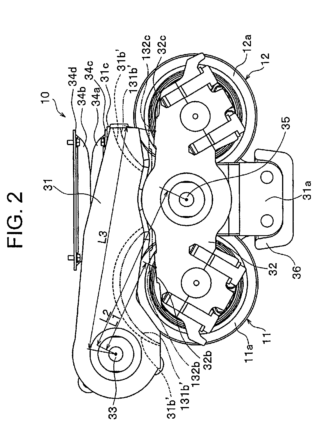
[0017]In the conventional double-bogie device, the apparent spring constant to the vehicle body load in the position in which the first lower track roller is supported in the end portion closer to the first arm base end portion of the second arm is set extremely higher than that in other positions (second lower track roller and immediately below the second turning fulcrum) on the second arm. Therefore, when the crawler runs over the raised contact area immediately below the first lower track roller, the operator is subjected to the large impact irrespective of the existence of the elastic member, and the operator has a feeling of fear of the falling height in the leading end portion of the crawler. The double-bogie device of the invention includes the spring constant equalizing unit to evenly distribute the apparent spring constant over a total length of the second arm. Accordingly, even if the crawler runs over the raised contact area, the falling height can be reduced in the leading end portion of the crawler while the impact is relaxed, and the feeling of fear can be removed.
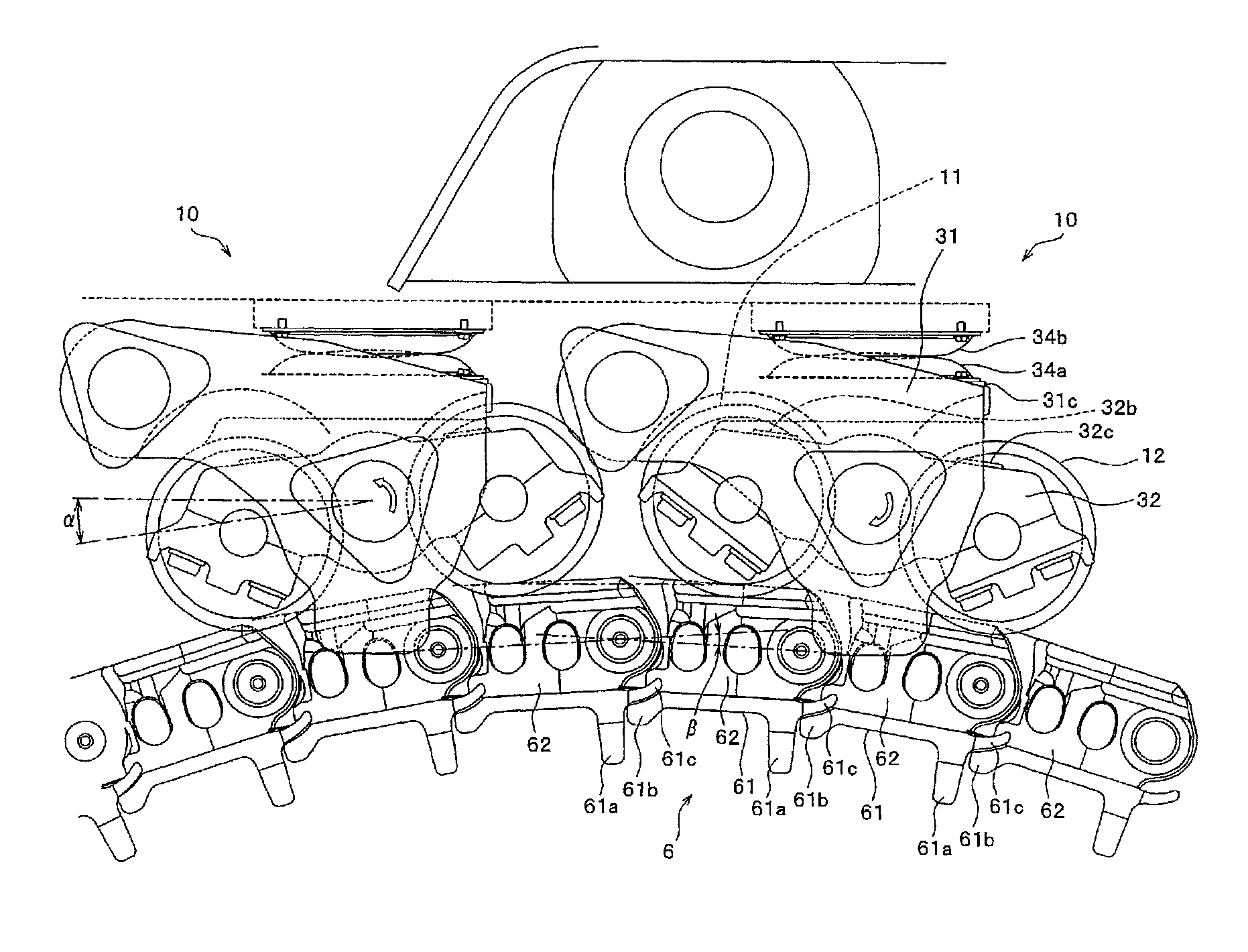
[0018]One of basic functions of the spring constant equalizing unit is that the maximum oscillation angle of the second arm is increased larger than the crossing angle of the connecting link in the maximum reverse camber of the crawler, so that the second arm supporting point (second turning fulcrum) of the first arm can always be subjected to the vehicle body load while the second arm does not abut on the first arm in the maximum reverse camber of the crawler. Additionally, because the second arm does not abut on the first arm, although the crossing angle of the connecting link is identical to that of the conventional one in the maximum reverse camber of the crawler, a slope angle of the track frame is relatively largely reduced by the increased oscillation angle of the second arm in the maximum reverse camber of the crawler, and thereby lowering the falling height of the leading end portion of the crawler. As a result, when the crawler runs over the raised contact area as described above, the falling height of the leading end portion of the crawler can be reduced while the impact is relaxed, and the feeling of fear of the falling height can be removed. In order to realize the effect, as described above, in at least one of the abutment surfaces of the first arm and second arm, the effect is realized by such simple forming that the abutment surface closer to the base end portion of the first arm is cut off to remove the thickness, or the bottom surface of an invasion recessed portion, which is formed closer to the base end portion of the first arm, of the first lower track roller is cut off to remove the thickness. Additionally, the effect can be obtained by cutting off at least one of the attaching surfaces of the elastic members fixed to the track frame and first arm.
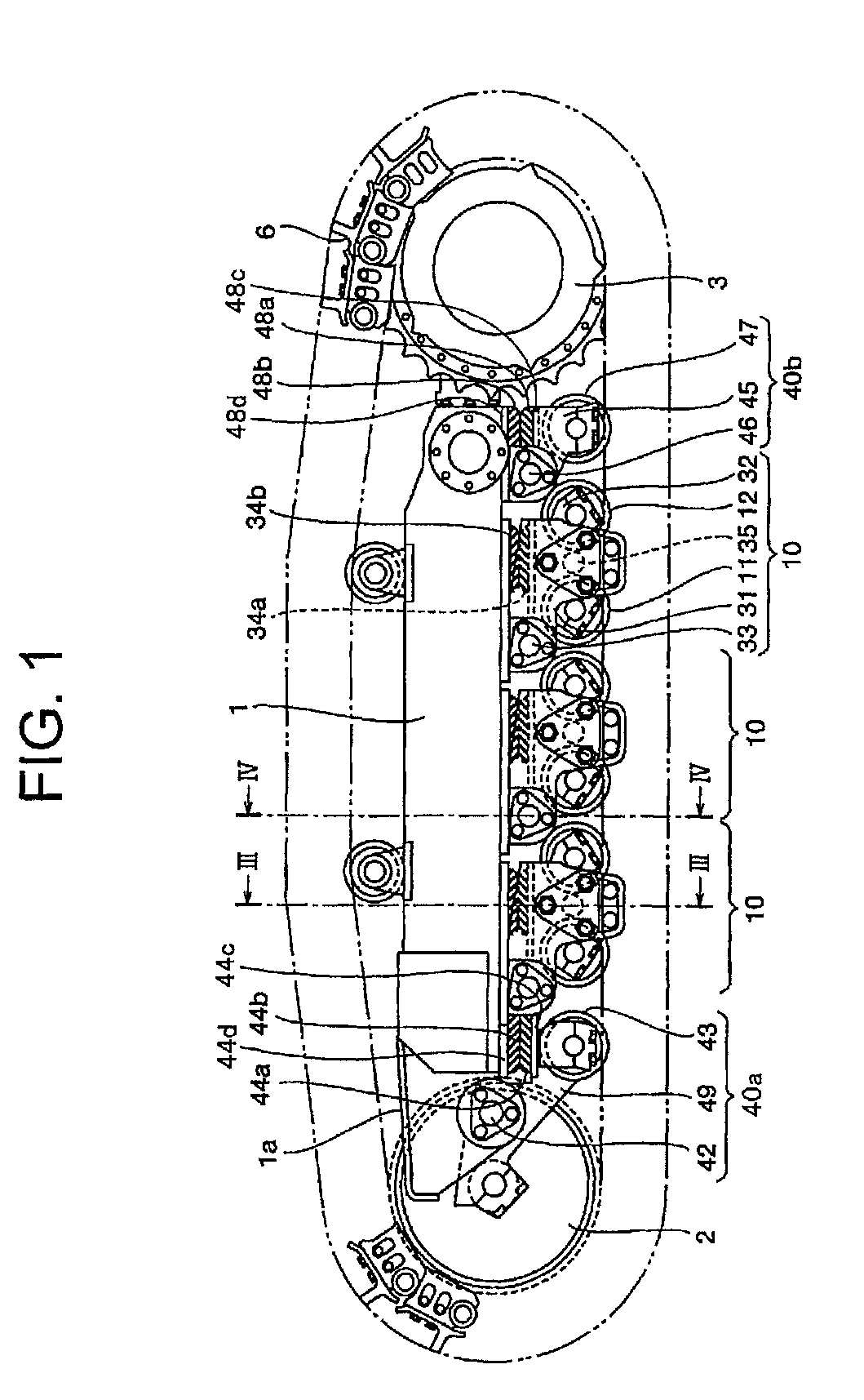
[0019]When the single-bogie devices are provided in front-back end portions of the track frame while the plurality of sets of double-bogie devices are provided between the single-bogie devices of the front-back end portions, the arm of the single-bogie device and the first arm of the double-bogie device can be subjected in the dispersed way to the vehicle body load of the work track-laying vehicle through the elastic members. Therefore, because the spring constant is equalized in each lower track roller position in running not only the flat contact area but also the raised contact area, the vehicle body load of the work track-laying vehicle can substantially evenly be dispersed to maintain the good ride quality of the work track-laying vehicle.

Problems solved by technology

Therefore, when the crawler runs over the raised contact area immediately below the first lower track roller, the operator is subjected to the large impact irrespective of the existence of the elastic member, and the operator has a feeling of fear of the falling height in the leading end portion of the crawler.

Method used


Image

  • Running device for track-laying vehicle
  • Running device for track-laying vehicle
  • Running device for track-laying vehicle

Examples


Embodiment Construction

[0031]A running device for track-laying vehicle according to a preferred embodiment of the invention will be described in detail with reference to the accompanying drawings. Hereinafter, a bulldozer is taken as an example of the track-laying vehicle to which the running device for track-laying vehicle of the invention is applied.

[0032]The running device of the embodiment will be described with reference to FIGS. 1 to 5. Referring to FIG. 1, a yoke 1a is mounted on one end portion of a track frame 1 while being movable in a longitudinal direction (front-back direction of vehicle), and a predetermined tension is applied to the yoke 1a with a spring (not illustrated) interposed between the yoke 1a and the track frame 1. An idler 2 is turnably attached to a leading end portion of the yoke 1a.

[0033]In the embodiment, a central portion in the longitudinal direction of the leading-end-portion arm 49 is attached to the yoke 1a mounted on one end portion of the track frame 1 by a pin 42 whi...


PUM


Abstract

There is provided a running device for track-laying vehicle, which can resolve a feeling of fear of falling height in a leading end portion of a crawler while relax a large impact when the crawler runs over a raised contact area. The running device includes a spring constant equalizing unit that equalizes an apparent spring constant of a second arm of lower track roller bogie device over a total length. The apparent spring constant is generated in maximum reverse camber of the crawler. The spring constant equalizing unit increases an oscillation angle α of the second arm that can abut on the first arm in the maximum reverse camber of the crawler such that the oscillation angle α of the second arm is larger than a crossing angle β of the connecting link. Desirably the increased maximum oscillation angle of the second arm is 1.3-2.0 times the crossing angle β.

Description

BACKGROUND OF THE INVENTION[0001]1. Field of the Invention[0002]The present invention relates to a running device for a track-laying vehicle in which a falling height of a nose is reduced while a local impact is relaxed when a crawler crosses over a projected running surface.[0003]2. Description of Related Art[0004]Conventionally, sometimes a bogie type (oscillation type) lower track roller, particularly a double-bogie type lower track roller is mounted on the widely used running device for the track-laying vehicle in order to improve ride quality during running. FIG. 9 illustrates a bulldozer that is of an example of the track-laying vehicle. The track-laying vehicle includes a pair of running devices in right and left lower portions of a vehicle body, and the running device includes a crawler 6. A track frame 1, an idler 2, a sprocket 3, and double-bogie devices 10 are provided in the running device. The track frame 1 is provided along a front-back direction of the vehicle. The id...

Claims


Application Information

Patent Timeline
Patent Type & Authority Patents(United States)
IPC IPC(8): B62D55/14
CPCB62D55/14B62D55/21B62D55/104
Inventor YOSHIDA, TSUYOSHIMITSUTA, SHINJINAKAMURA, SHINYATSUMURA, SOUICHIYAMASHITA, TETSUNORI
Owner KOMATSU LTD
Learn More