
Artificial molar teeth

a technology of artificial teeth and molars, applied in the field of artificial teeth, can solve the problems of difficult to arrange the opposing artificial molar teeth in an appropriate positional relation, require advanced skill and experience, and it is extremely difficult to make dentures for each patien

Inactive Publication Date: 2014-04-15
SHOFU INC
View PDF8 Cites 0 Cited by
  • Summary
  • Abstract
  • Description
  • Claims
  • Application Information

AI Technical Summary

Benefits of technology

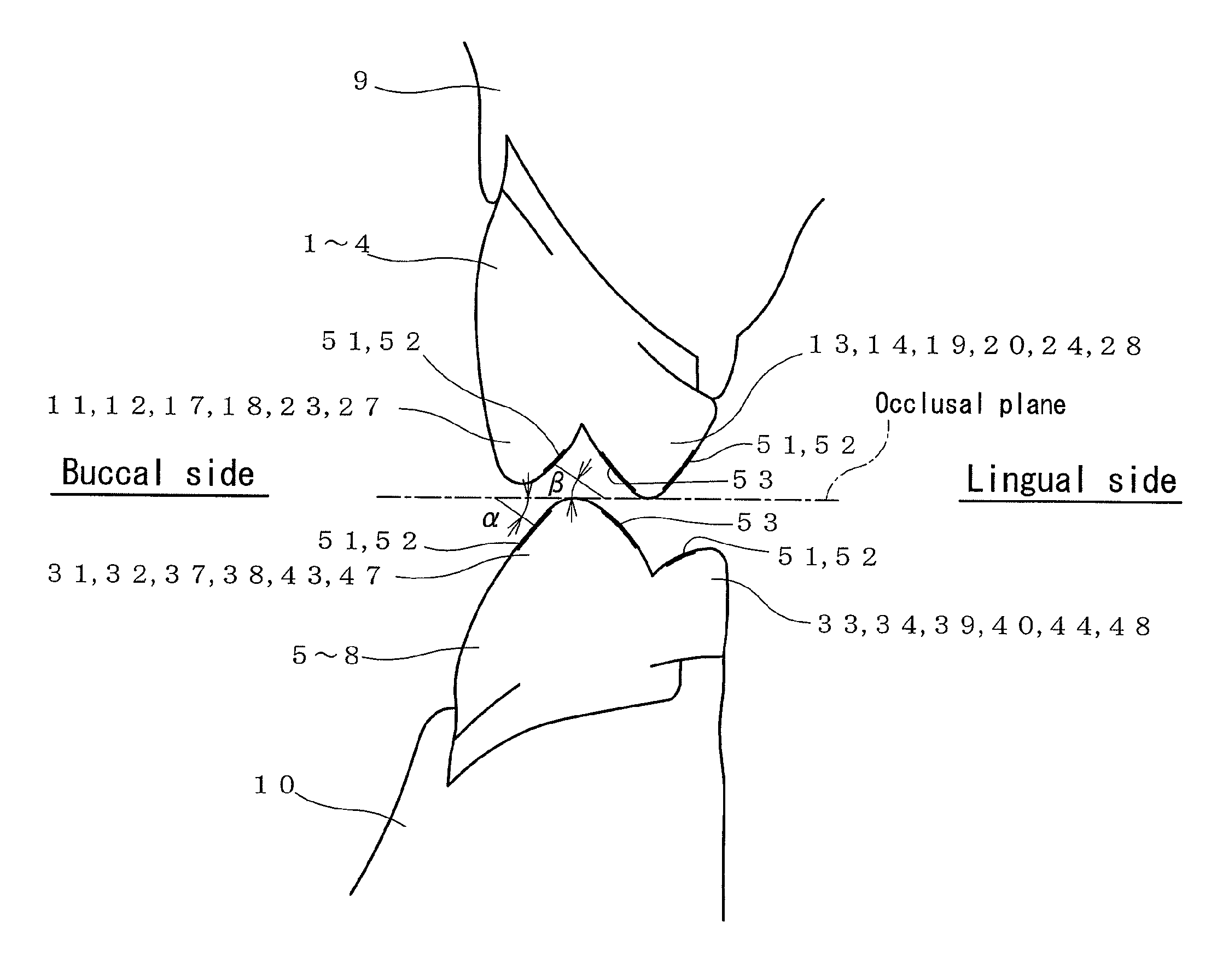
The present invention provides artificial molar teeth that can be easily arranged in a patient's mouth without requiring advanced skill and experience. The teeth are designed with different vertical line angles between the occlusal facet of the mandibular and maxillary molar teeth, which allows for easier arrangement without the need for precise positioning. This reduces the manufacturing cost and simplifies the process of making a denture.

Problems solved by technology

However, the arrangement required advanced skill and experience, and it was particularly difficult to arrange the opposing artificial molar teeth in an appropriate positional relation.
In the artificial molar teeth of JP-A-2002-177301, however, it is required to occlude and contact between the lingual cusps of the maxillary molar teeth and the fossae of the antagonist mandibular molar teeth, and between the fossae of the maxillary molar teeth and the buccal cusps of the antagonist mandibular molar teeth, respectively, and therefore it was extremely difficult to make dentures for each patient depending on the complex oral cavity environment of each patient.
Still worse, distortion of molding may occur in the cusps of artificial teeth in a molding process, and therefore it is very difficult to mold the cusps in a shape to be exactly engaged with the fossae of the antagonist molar teeth, causing a disadvantage of poor yield ratio.
Therefore, a process in making denture is long and complicated, and the patient's burden is also large.

Method used


Image

  • Artificial molar teeth
  • Artificial molar teeth
  • Artificial molar teeth

Examples


Embodiment Construction

[0031]An embodiment of the present invention is described below with reference to the drawings.

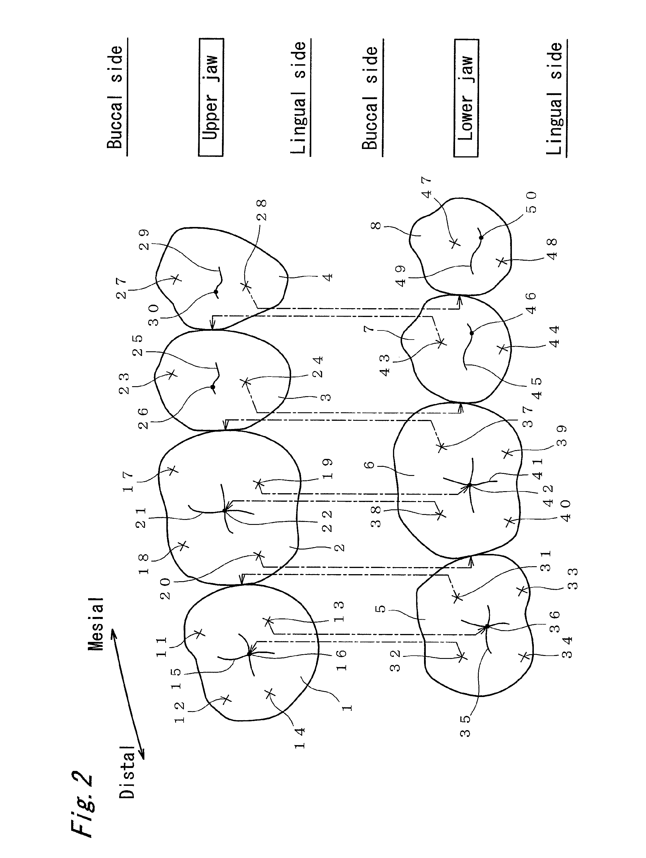
[0032]The present invention relates to a technique of making artificial teeth as a dental prosthetic appliance as a denture and, especially to a technique capable of applying for making artificial molar teeth. The artificial molar teeth include a first molar tooth, a second molar tooth, a first premolar tooth, and a second premolar tooth, and a combination of at least one pair of maxillary and mandibular antagonist teeth may be preferred.

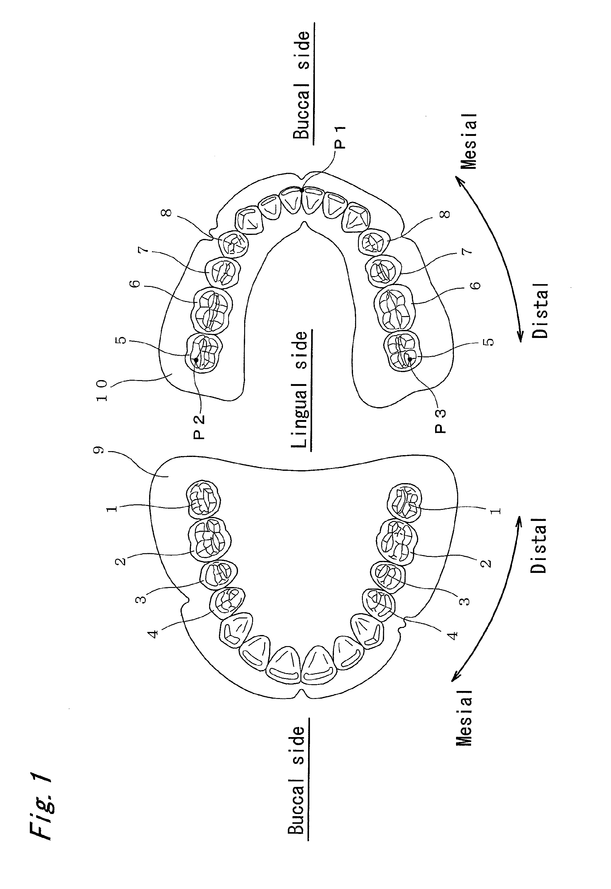
[0033]FIG. 1 shows a general arrangement of all artificial teeth, in which the left side shows the upper jaw, and the right side shows the lower jaw. In the artificial teeth, one maxillary tooth corresponds to one mandibular tooth. The artificial molar teeth may be made of any medical material including ceramic teeth, resin teeth, or composite artificial teeth. In the following explanation, a direction approaching the anterior teeth (central incisor) refer...


PUM


Abstract

Maxillary molar teeth and mandibular molar teeth are formed so as to be different in intersection angles (vertical line angles) between vertical lines extending in a vertical direction to occlusal facets and occlusal planes. That is, the maxillary molar teeth and the mandibular molar teeth are formed so as to be different in intersection angles of vertical lines of the protrusive occlusal facet and retrusive occlusal facet respectively. The occlusal facets of at least one of buccal cusps of the maxillary molar teeth and lingual cusps of the mandibular molar teeth are designed so that at least one of the width in the mesiodistal direction and the width in the cuspal-cervical direction is smaller than the occlusal facets of the opposite cusps of the antagonist molar teeth.

Description

BACKGROUND OF THE INVENTION[0001]1. Field of the Invention[0002]The present invention relates to artificial molar teeth which can be arranged easily when making a dental prosthetic appliance and are easy in mastication when dentures are worn and, more particularly to artificial molar teeth in which an angle of occlusal facets of maxillary molar teeth is different from an angle of occlusal facets of mandibular molar teeth.[0003]2. Description of the Related Art[0004]In making a dental prosthetic appliance, it has been considered important to maintain the relation of the cusps and the contour parts of the maxillary and mandibular antagonist molar teeth. Thus, an arrangement of artificial molar teeth has been demanded to be stable in shape by making contact between a plurality of cusps and contour part. It has been further demanded to be free from the work of grinding largely after the arrangement, or changing the surface state largely. However, the arrangement required advanced skill ...

Claims


Application Information

Patent Timeline
Patent Type & Authority Patents(United States)
IPC IPC(8): A61C13/08
CPCA61C13/097
Inventor KADOBAYASHI, YUSEI
Owner SHOFU INC
Learn More