
Power module and power conversion device

a power module and power conversion technology, applied in the field of power modules, can solve the problems of increasing the size of the power conversion device along with the size increase, affecting the insulation performance of the resin insulation material itself, and affecting the insulation reliability of the power module and the power conversion device. to achieve the effect of improving the insulation reliability of the power module and the power conversion devi

Inactive Publication Date: 2014-03-18
HITACHI ASTEMO LTD
View PDF14 Cites 14 Cited by
  • Summary
  • Abstract
  • Description
  • Claims
  • Application Information

AI Technical Summary

Benefits of technology

[0023]According to the present invention, it is possible to enhance the insulation reliability of a power module and of a power conversion device including this module.

Problems solved by technology

While, by increasing the size of the power semiconductors, it is possible to reduce the thermal resistance with respect to the cooling medium by increasing the heat dissipation area, on the other hand the size of the power conversion device increases along with increase in size of the power semiconductors, and at the same time the productivity is also deteriorated.
However, the insulation performance of the resin insulation material itself is inferior as compared to a ceramic, and, since permeation of the cooling medium or moisture from outside exerts a negative influence upon the performance for adhesion to the cooling device and upon the insulating performance, accordingly there is a problem in the field of application to in-vehicle devices, for which high reliability is demanded.
With the construction disclosed in Patent Document #4, there is the problem that heat dissipation is performed from only one surface of the power semiconductors, so that the cooling performance is low.
If the cooling medium should seep in, then the adhesive strength of the insulating adhesive and the insulation performance between the insulating adhesive and the inorganic insulation layer itself will deteriorate, and as a result it will become impossible to maintain the insulation performance of the insulating substrate.
This is a problem in the field of equipment for vehicles, for which high reliability is demanded.

Method used


Image

  • Power module and power conversion device
  • Power module and power conversion device
  • Power module and power conversion device

Examples


embodiment 1

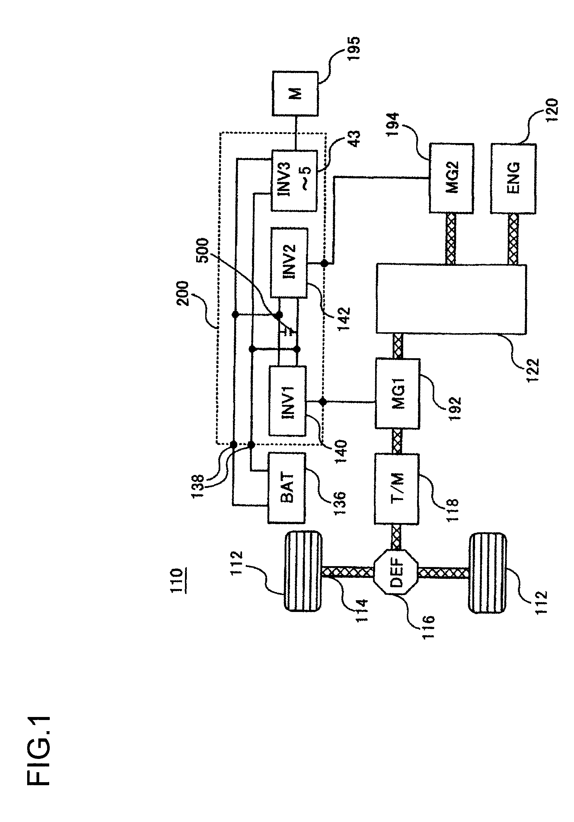
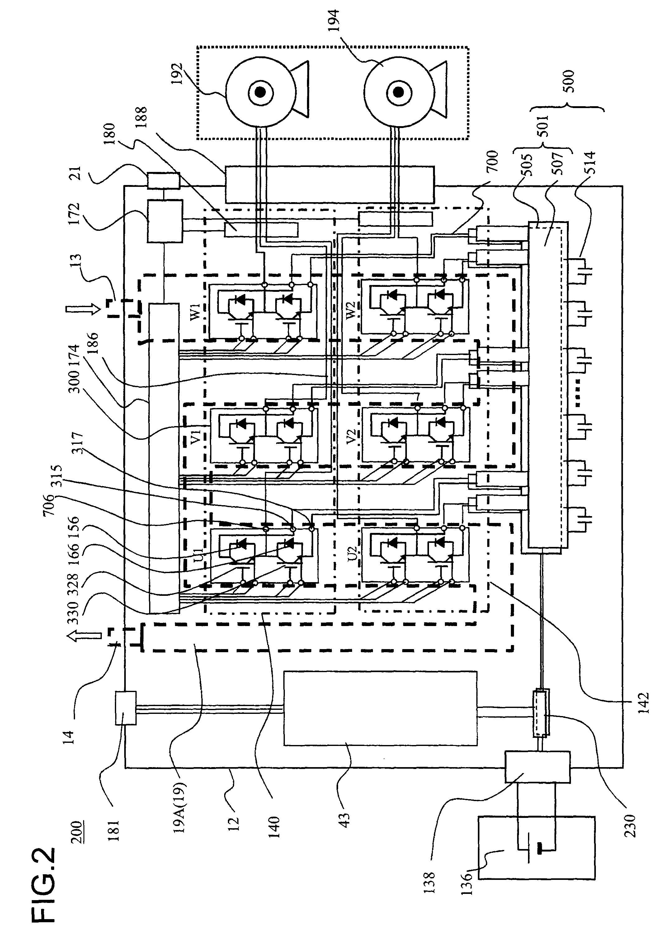
[0048]FIG. 1 is a figure showing control blocks of a hybrid vehicle. In FIG. 1, a hybrid electric vehicle (hereinafter termed a HEV) 110 is a kind of electrically powered vehicle that includes two systems for vehicle driving. One of these systems is an engine system that employs an engine 120, that is an internal combustion engine, as a power source. This engine system is principally used as a source of driving power for the HEV 110. The other system is an in-vehicle electric motor system that employs a motor-generator MG1192 and a motor-generator MG2194 as power sources. The in-vehicle electric motor system is principally used as a driving source for the HEV 110 and as a power generation source for the HEV 110. The motor-generators MG1192 and MG2194 may be, for example, synchronous machines or induction machines, and since they can be used both as motors and as generators depending upon the manner in which they are operated, in this specification they will be termed “motor-generato...

embodiment 2

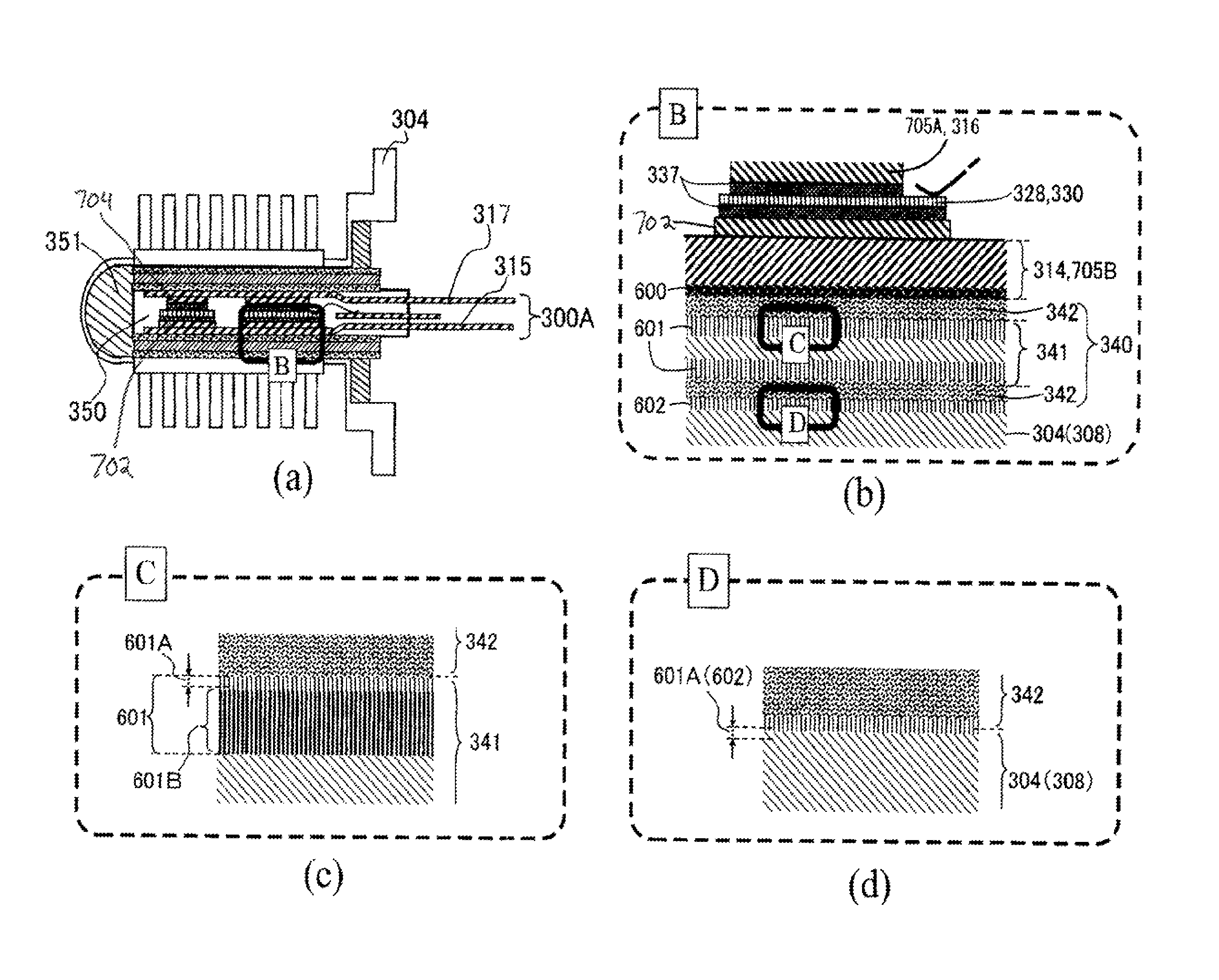
[0134]FIG. 11(a) is a sectional view of a power module 300 according to another embodiment, and FIG. 11(b) is an exploded sectional view of this power module 300 according to another embodiment. While the portions that differ from the first embodiment are explained below, structures to which the same reference symbols are appended as in the first embodiment have the same functions.

[0135]In this embodiment, instead of the insulation sheets 333 according to the first embodiment, aluminum insulation plates 340 are provided. Thin insulating resin layers 342 having good adhesive quality are formed on both of the principal surfaces of each of these aluminum insulation plates 340. An alumite plate 341 is sandwiched between these two layers 342 of insulating resin, and moreover alumite processing is performed upon the entire assembly, so that alumite layers 601 are formed upon its front and rear surfaces. The alumite plate 341 and the two insulating resin layers 342 are adhered together by ...

embodiment 3

[0143]FIG. 16(a) is a sectional view of a power module 300 according to another embodiment, and FIG. 16(b) is a sectional view of this power module 300 according to another embodiment during assembly. While the portions that differ from the first embodiment are explained below, structures to which the same reference symbols are appended as in the first embodiment have the same functions.

[0144]In this embodiment, instead of the can type cooling device 304 according to the first and second embodiment, flow conduit defining members 380A and 380B are employed within which internal flow conduits 381 are defined. As shown in FIG. 16(b), alumite processing as explained for the first embodiment is performed upon the surfaces 382A and 382B of these flow conduit defining members 380A and 380B that contact against the insulation sheets 333.

[0145]Due to this, it is not necessary to form the organic acid type alumite layer 601B upon the interior plane surfaces 308 of the can type cooling device ...


PUM

PropertyMeasurementUnit
voltageaaaaaaaaaa
thicknessaaaaaaaaaa
thicknessaaaaaaaaaa

Abstract

A power module according to the present invention includes: a semiconductor element for converting DC current to AC current by switching operation; an electrical wiring board to which the semiconductor element is electrically connected, with the semiconductor element being disposed upon one of its principal surfaces; an insulating resin layer provided on the other principal surface of the electrical wiring board; a first insulation layer that is disposed opposite from the electrical wiring board, separated by the insulating resin layer, and that is joined to the insulating resin layer; a second insulation layer that is disposed opposite from the insulating resin layer, separated by the first insulation layer, and that ensures electrical insulation of the semiconductor element; and a metallic heat dissipation member that is disposed opposite from the first insulation layer, separated by the second insulation layer, and that radiates heat generated by the semiconductor element via the electrical wiring board, the insulating resin layer, the first insulation layer, and the second insulation layer.

Description

TECHNICAL FIELD[0001]The present invention relates to a power module that internally houses an inverter circuit, and to a power conversion device that incorporates such a power module.BACKGROUND ART[0002]With a prior art power module of the type that is cooled on both sides, electrical wiring, an insulation layer, and a cooling device are provided on one principal surface upon which electrodes of internal power semiconductor elements are formed, and also electrical wiring, an insulation layer, and a cooling device are provided, in a similar manner, on its other principal surface as well. A heat dissipation base and fins are formed on the side opposite to the side where the power semiconductor devices are placed, which, moreover, are dipped into the water passage housing internal to the cooling device described above, in which a cooling water passage is formed by sealing with resin material, through which the fins become in direct contact with the cooling medium and thus the heat gen...

Claims


Application Information

Patent Timeline
Patent Type & Authority Patents(United States)
IPC IPC(8): H05K7/20B60L50/15B60L50/16
CPCY02T10/6239H02M7/003H01L25/072B60L2200/10Y02T10/70H01L2924/13055H01L23/433H01L23/467Y02T10/6217B60L2220/14H01L2224/8384H01L24/33B60L3/003B60L11/14B60L2200/36B60L2240/525H01L2224/83101B60K6/445B60K1/02H01L2924/13091H01L23/367B60L2200/32B60L2200/26H01L2224/73265B60L11/123B60L2220/12H01L2924/01327Y02T10/7077B60L2240/36B60K6/365H01L2924/07802H01L2924/1306H01L2924/1305H01L2924/181C25D11/08C25D11/10C25D11/12H01L23/473B60L50/61B60L50/16Y02T10/62Y02T10/7072H01L2924/00
Inventor TOKUYAMA, TAKESHINAKATSU, KINYASAITO, RYUICHISATOH, TOSHIYAISHIKAWA, HIDEAKI
Owner HITACHI ASTEMO LTD
Learn More