
Method for attaching a particle to a scanning probe tip through eutectic bonding

a technology of eutectic bonding and probe tip, which is applied in the field of probe and a method for attaching a particle to the apex can solve the problems of increasing the cross sectional area and the surface roughness of the probe tip, inconvenient application of the method, and difficult control, so as to achieve the effect of correctly and accurately attaching a conductive particle to the apex and no expensive equipmen

Inactive Publication Date: 2014-02-18
NATIONAL TSING HUA UNIVERSITY
View PDF21 Cites 2 Cited by
  • Summary
  • Abstract
  • Description
  • Claims
  • Application Information

AI Technical Summary

Benefits of technology

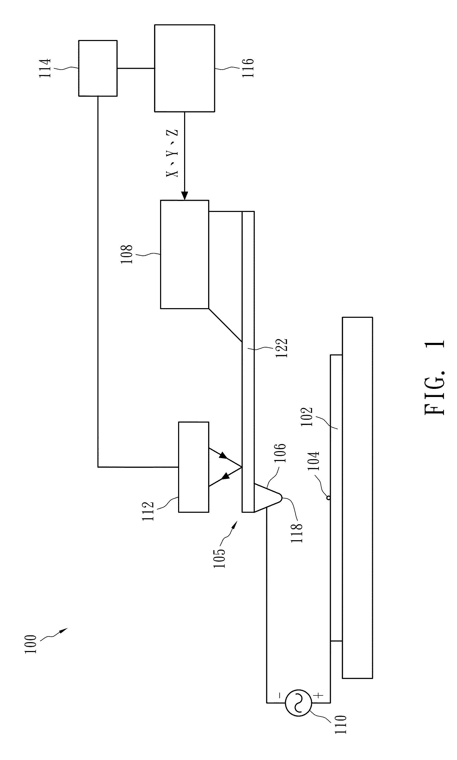
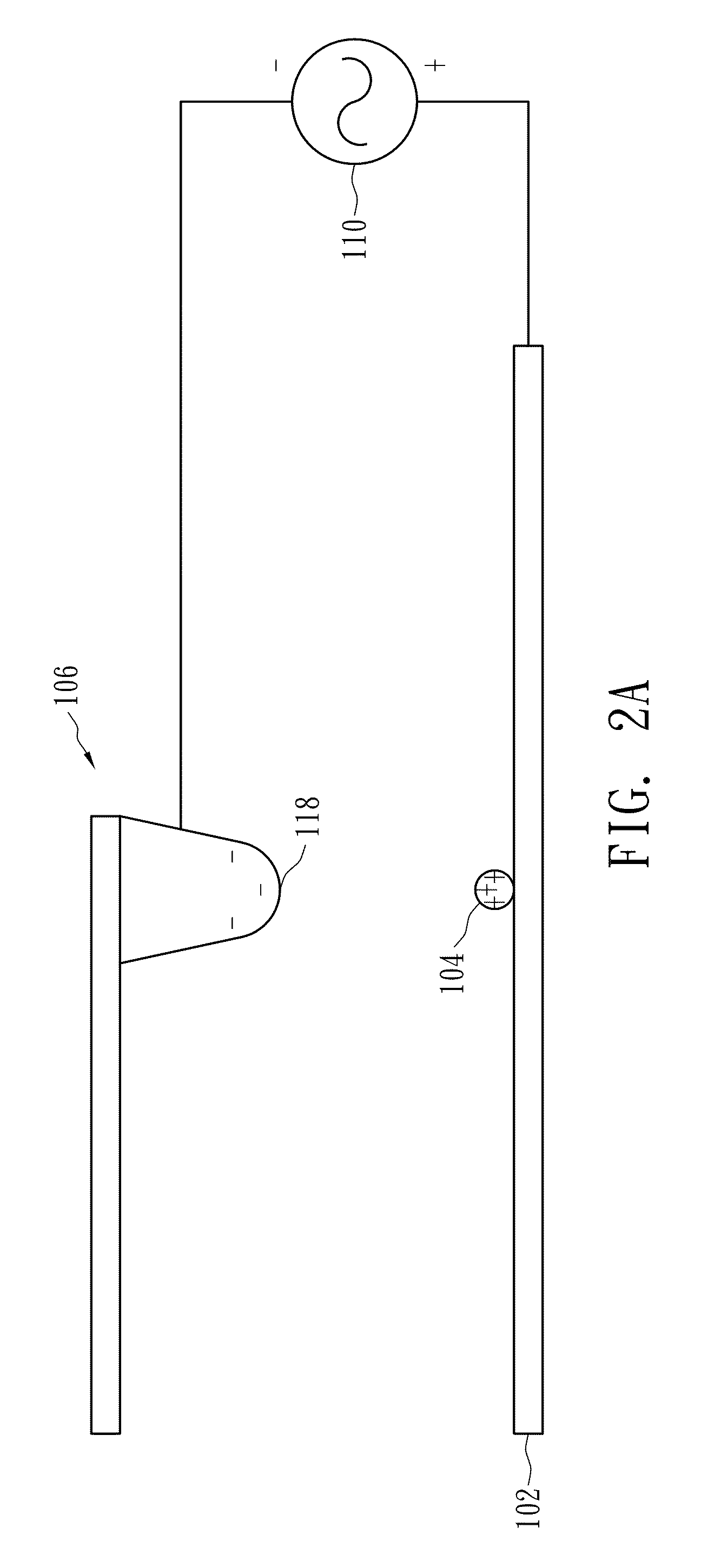
[0010]The present invention provides a scanning probe and a method for attaching a conductive particle to the apex of the probe tip of the scanning probe. The method uses a bias voltage to directly move and attach a conductive particle to the apex of the probe tip of a scanning probe. The method requires no surface treatment of the probe tip and no expensive equipment, and can correctly and accurately attach a conductive particle to the apex.
[0014]Compared with prior art methods, the surface of the probe tip does not need to be treated to have a particle attachable layer so that the configuration of the outer surface of the probe tip does not change. Because there is no requirement for surface treatment of the probe tip, the complex process steps for surface treatment can be omitted and the manufacturing cost reduced. The method of the present invention can be performed with simple equipment so as to have a low cost advantage. The method of the present invention controls the apex to directly engage the target conductive particle so that the conductive particle can be correctly attached to the apex of the probe tip, and therefore can achieve good yield. In contrast, the prior art methods cannot control a particle effectively to attach it to the preferred location so that good yield cannot be achieved.

Problems solved by technology

However, the method requires several chemical processes to form an attach layer on the surface of the probe tip, and these chemical processes may increase the cross sectional area and the surface roughness of the probe tip.
Furthermore, to attach nanoparticles of different materials or to use a probe tip of different material, different SAMs are required so that the application of the method is inconvenient.
In addition, to attach a single nanoparticle to the top of a probe tip by the method requires careful control of parameters such as the concentration of nanoparticle suspension, the probe tip immersion time, and the method of immersing the probe tip, and such parameters are difficult to control during mass production.
Because the method requires an illumination system that can generate the evanescent wave and equipment for depositing titanium oxide, the manufacturing cost of the probe tip fabricated by the method is high.
In addition, the method cannot precisely control the size of the deposited gold particle, and therefore, it is difficult to maintain good quality control.
In summary, there is no method that can be applied to attach a particle to the top of a probe tip that has no unwanted effects and that is cost effective for utilization by the industry.

Method used


Image

  • Method for attaching a particle to a scanning probe tip through eutectic bonding
  • Method for attaching a particle to a scanning probe tip through eutectic bonding
  • Method for attaching a particle to a scanning probe tip through eutectic bonding

Examples


Embodiment Construction

[0021]FIG. 1 shows an apparatus 100 for firmly attaching a conductive particle to the apex of a probe tip according to one embodiment of the present invention. The apparatus 100 for firmly attaching a conductive particle to the apex of a probe tip is configured to attractively and firmly attach a conductive particle 104 placed on the surface of a conductive substrate 102 to the apex of a probe tip 106, which comprises a probe drive device 108, a waveform generator 110, an analysis circuit 114, and a controller 116. The cantilever arm 122 of the scanning probe 105 is coupled to the probe drive device 108, which is configured to make the probe tip 106 stationary and to move the probe tip 106 during a scanning process. The waveform generator 110 electrically coupled to the probe tip 106 and the conductive substrate 102 is configured to apply a bias voltage between the probe tip 106 and the conductive substrate 102 such that when a bias voltage is applied between the probe tip 106 and t...


PUM


Abstract

A method for attaching a conductive particle to the apex of a probe tip comprises the steps of: moving the apex of a probe tip close to a conductive particle and applying a bias voltage between the probe tip and the conductive particle so that the conductive particle can permanently attach to the apex. The method uses only a bias voltage to transfer and attach conductive particles to the apex of a probe tip, and no surface treatment of the probe tip is required.

Description

BACKGROUND OF THE INVENTION[0001]1. Field of the Invention[0002]The present invention relates to a probe and a method for attaching a particle to the apex of a probe tip, and relates more particularly to a probe and a method for attaching a conductive particle to the apex of a probe tip with the application of a bias voltage.[0003]2. Description of the Related Art[0004]Scanning probe microscopy (SPM) is applied for depiction or measurement of the details of fine-scale surface features and material characteristics, and such depiction or measurement is usually performed using a sharp probe tip to scan a target surface.[0005]The probe tip is fixed to one end of a cantilever beam such that the probe tip can move following the profile of a target surface by means of the cantilever beam while scanning. During scanning, the probe tip moves up and down due to the weak interaction forces between atoms on the apex of the probe tip and on the target surface. By measuring the distances of the u...

Claims


Application Information

Patent Timeline
Patent Type & Authority Patents(United States)
IPC IPC(8): G01Q60/38G01Q70/18G01Q60/40
CPCB82Y35/00B82Y15/00G01Q60/40
Inventor TSENG, FAN GANGCHENG, HUI WENJHENG, WUN YUAN
Owner NATIONAL TSING HUA UNIVERSITY
Learn More