
Manufacturing apparatus of polycrystalline silicon

a manufacturing apparatus and polycrystalline silicon technology, applied in the direction of silicon compounds, condensed vapors, crystal growth processes, etc., can solve the problems of insufficient deposited polycrystalline silicon on these portions, and achieve the effect of improving workability and productivity of manufacturing polycrystalline silicon and preventing falling down

Active Publication Date: 2014-02-18
HIGH-PURITY SILICON CORP
View PDF12 Cites 2 Cited by
  • Summary
  • Abstract
  • Description
  • Claims
  • Application Information

AI Technical Summary

Benefits of technology

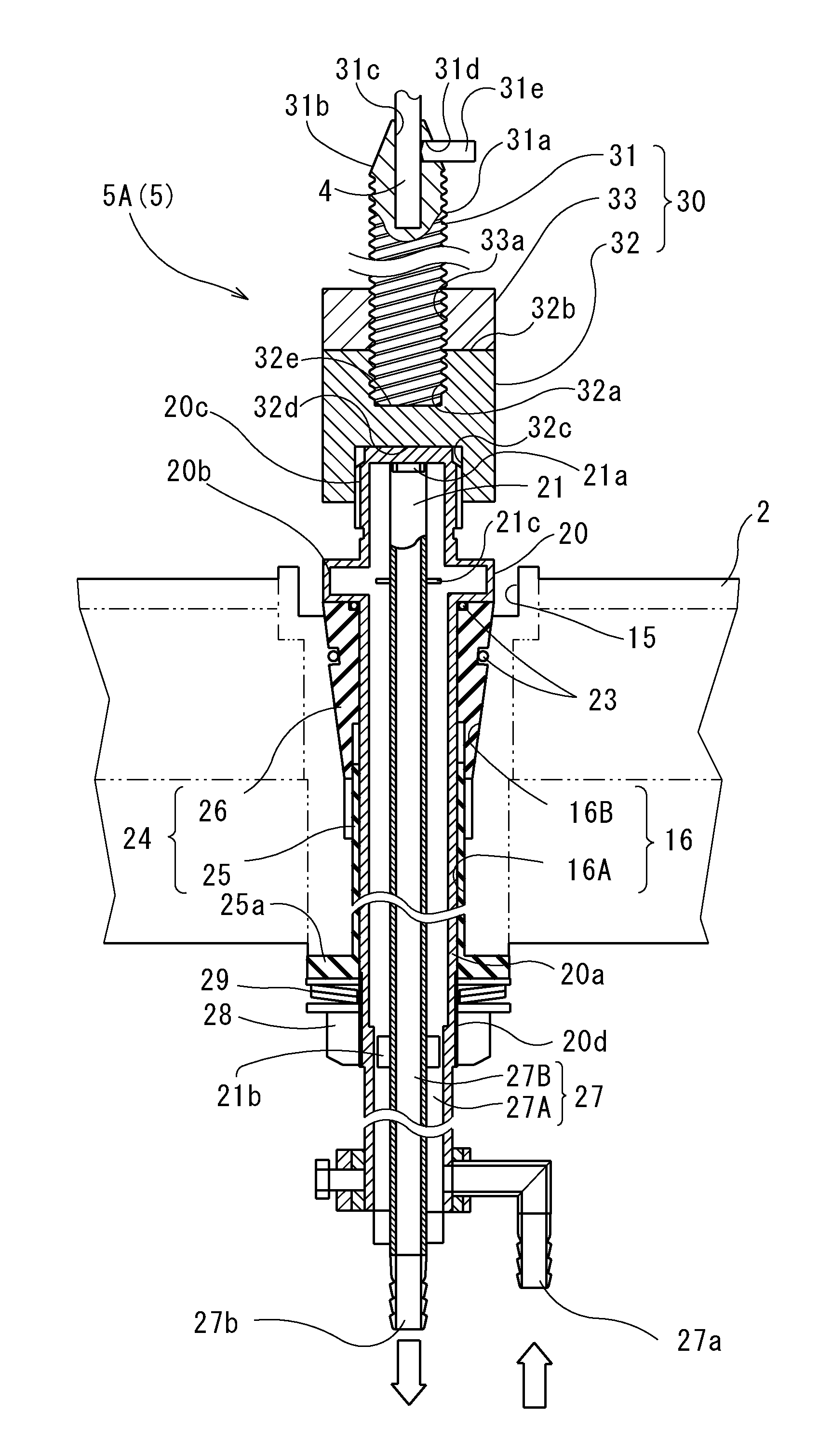
The present invention relates to a manufacturing apparatus of polycrystalline silicon. The technical effects of the invention include: 1) it is easy to cool the seed rod holding member because the heat cap is interposed between the seed rod holding member and the electrode holder, preventing the polycrystalline silicon from cooling too quickly and causing it to fall down; 2) the temperature of the seed rod holding member is maintained high, allowing the polycrystalline silicon to be securely supported and prevented from falling down; 3) the polycrystalline silicon is deposited on the entire surface of the silicon seed rod and the lower-end portion of the seed rod holding member, ensuring strong support and preventing it from falling down, thereby improving the workability and productivity of manufacturing polycrystalline silicon. Additionally, the invention allows for the easy reuse of the electrode members such as the heat cap and the like, reducing production costs.

Problems solved by technology

In this case, the fallen polycrystalline silicon may damage a furnace floor of the reactor, or may short-circuit between the electrodes and the furnace floor, so that the reaction is prevented from continuing.
As a result, polycrystalline silicon is not deposited enough on these portions.

Method used


Image

  • Manufacturing apparatus of polycrystalline silicon
  • Manufacturing apparatus of polycrystalline silicon
  • Manufacturing apparatus of polycrystalline silicon

Examples


Embodiment Construction

[0019]Below, an embodiment of the present invention will be described with reference to drawings.

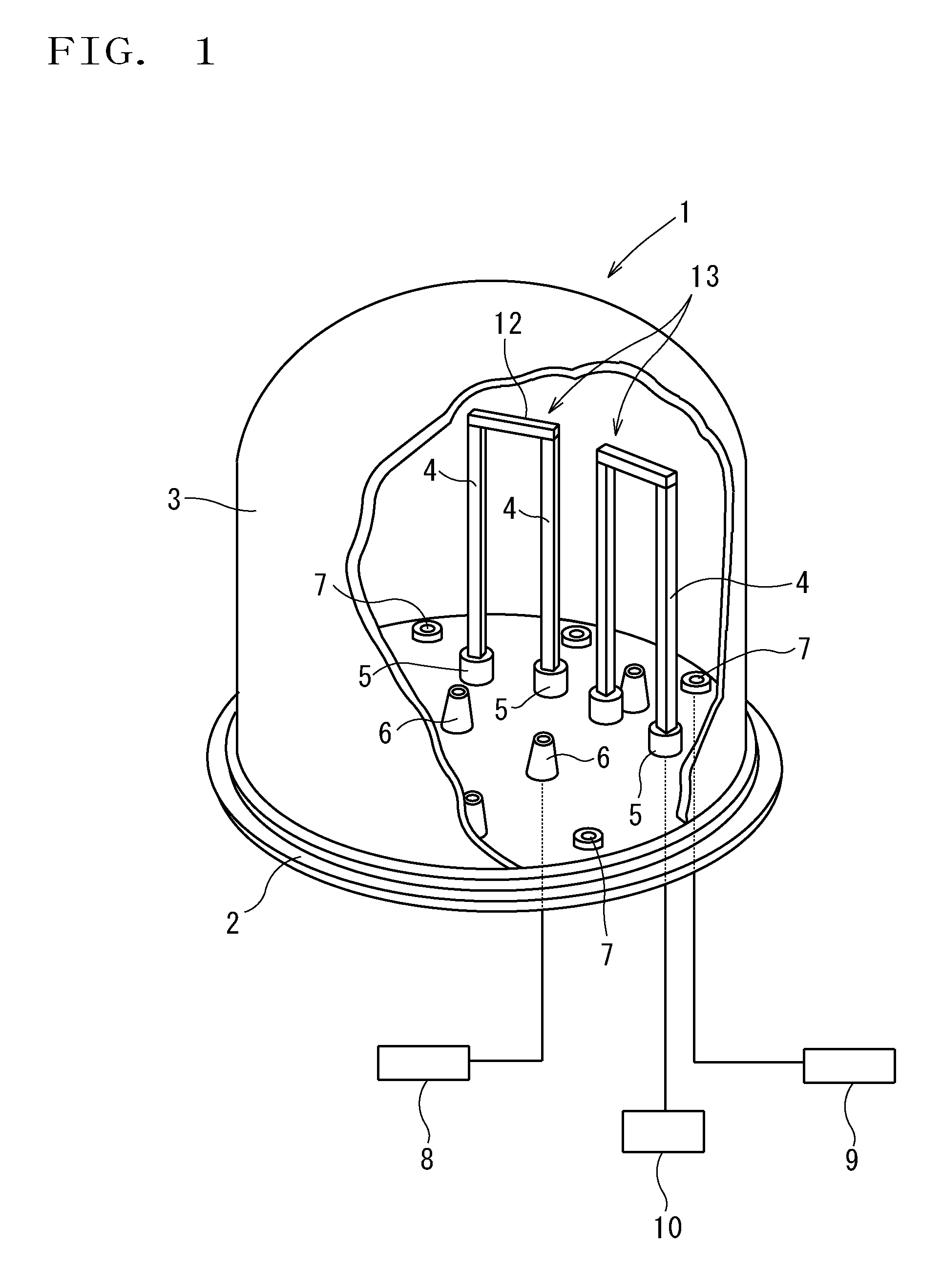
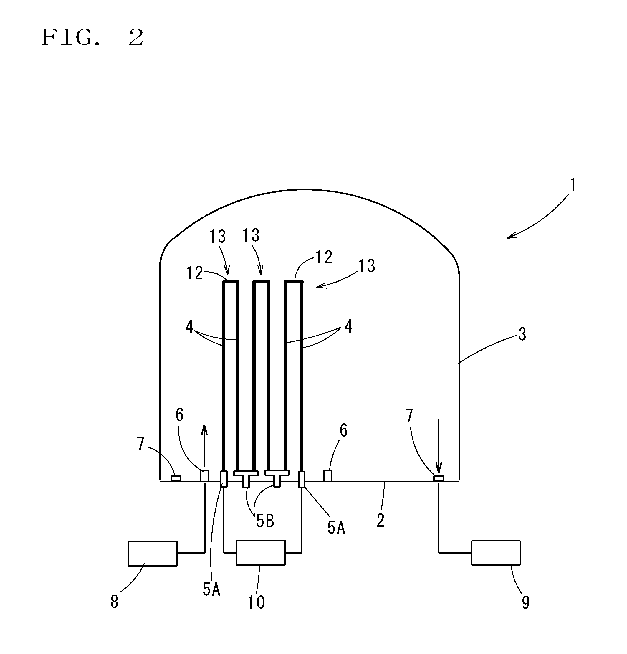
[0020]FIG. 1 is an overall view of a manufacturing apparatus of polycrystalline silicon of the present invention. A reactor 1 of the manufacturing apparatus of polycrystalline silicon is provided with: a bottom plate portion 2 which forms a furnace floor; and a bell jar 3 which is detachably attached to bottom plate portion 2. The upper surface of the bottom plate 2 is substantially a flat horizontal surface. The bell jar 3 has a hanging-bell shape as a whole, and a roof thereof is domical. Therefore, an inner space of the bell jar 3 is the highest at a center portion, and is the lowest at a peripheral portion. The bottom plate portion 2 and a wall of the bell jar 3 form a jacket structure (not illustrated), and are cooled by coolant.

[0021]A plurality of electrode units 5 to which silicon seed rods 4 are attached, a plurality of injection nozzles (i.e., gas-supply ports) 6 to inject raw-...


PUM

PropertyMeasurementUnit
electric currentaaaaaaaaaa
inclined angleaaaaaaaaaa
melting pointaaaaaaaaaa

Abstract

A manufacturing apparatus of polycrystalline silicon products polycrystalline silicon by depositing on a surface of a silicon seed rod by supplying raw-material gas to the heated silicon seed rod provided vertically in a reactor, includes: an electrode which holds the silicon seed rod and is made of carbon; an electrode holder which holds the electrode, and cooled by coolant medium flowing therein, wherein the electrode includes: a seed rod holding member which holds the silicon seed rod; a heat cap which is provided between the seed rod holding member and the electrode holder; and a cap protector having a ring-like plate shape, which covers an upper surface of the heat cap, and in which a through hole penetrating the lower-end portion of the seed rod holding member is formed.

Description

BACKGROUND OF THE INVENTION[0001]1. Field of the Invention[0002]The present invention relates to a manufacturing apparatus of polycrystalline silicon that products rods of polycrystalline silicon by depositing polycrystalline silicon on surfaces of heated silicon seed rods.[0003]Priority is claimed on Japanese Patent Application No. 2008-231163, filed Sep. 9, 2008, the content of which is incorporated herein by reference.[0004]2. Description of the Related Art[0005]Conventionally, a manufacturing apparatus of polycrystalline silicon by the Siemens process is known. In the manufacturing apparatus of polycrystalline silicon by the Siemens process, a plurality of silicon seed rods are provided in a reactor and heated. Raw-material gas including chlorosilane gas and hydrogen gas is supplied into the reactor and in contact with the heated silicon seed rods, so that polycrystalline silicon is deposited on the surface of the silicon seed rods by thermal decomposition and hydrogen reduction...

Claims


Application Information

Patent Timeline
Patent Type & Authority Patents(United States)
IPC IPC(8): C30B25/00
CPCC01B33/035Y10T117/10Y10T117/1016
Inventor ENDOH, TOSHIHIDETEBAKARI, MASAYUKIISHII, TOSHIYUKISAKAGUCHI, MASAAKI
Owner HIGH-PURITY SILICON CORP
Learn More