Method for the calibration of a flow measurement in a flow system, and flow system for carrying out the method

a flow system and flow measurement technology, applied in the direction of instruments, liquid/fluent solid measurement, testing/calibration of volume flow, etc., can solve the problems of increasing demands on flow measurement, inability to keep pace, and increased efforts

Active Publication Date: 2014-01-21
THORATEC CORPORTION
View PDF8 Cites 10 Cited by
  • Summary
  • Abstract
  • Description
  • Claims
  • Application Information

AI Technical Summary

Benefits of technology

[0019]It is an object of the present invention to make available a method for the calibration of a flow rate in a flow system, in particular in a portable ventricle support system, and also a flow system, especially a ventricle support system, with which the flow rate of the fluid can be determ

Problems solved by technology

It is barely possible to keep pace with the number of methods and applications which are now known for the measurement of flow, in other words for the determination of the amount of a fluid that is pumped through a flow system per unit of time.
Greater efforts have to be made, however, when the demands on the flow measurement increase.
Depending on the method of measurement, other parameters, such as the viscosity of the fluid for example, which can change in the course of the measuring process, can unacceptably influence the results.
However, not only can the measuring apparatus be affected negatively by the fluid to be measured; vice versa, in some cases the measuring apparatus can also have negative repercussions on the fluid to be measured.
In the case of a mechanical bearing for example, in which an impeller is journalled for the measurement of the flow rate, this can lead to contaminati

Method used


Image

  • Method for the calibration of a flow measurement in a flow system, and flow system for carrying out the method
  • Method for the calibration of a flow measurement in a flow system, and flow system for carrying out the method
  • Method for the calibration of a flow measurement in a flow system, and flow system for carrying out the method

Examples


Embodiment Construction

[0032]One possible concept for the determination of the flow from the corresponding power curves of the pump or of the pump drive will be explained in the following.

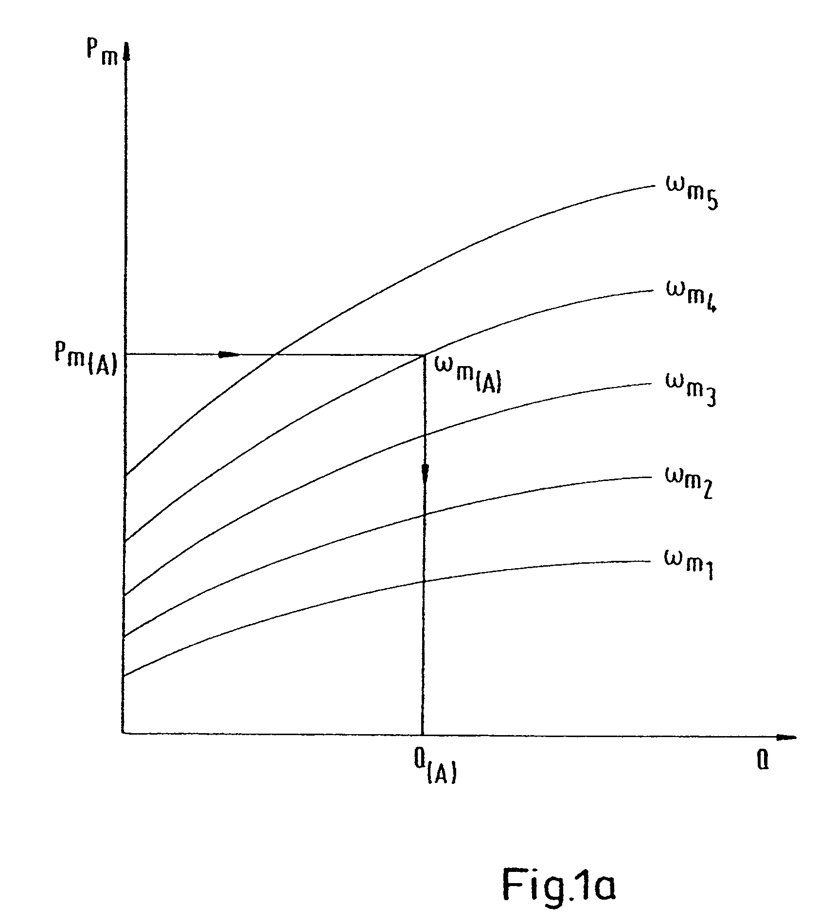
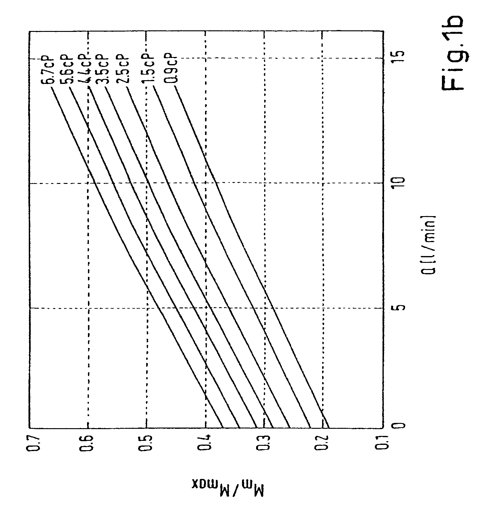
[0033]The symbols used, such as are also to be found in part in FIGS. 1a and 1b, normally have in this connection the following meaning: Pm is the mechanical power delivered at the rotor; M is the total motor torque; Mm is the mechanical torque delivered at the rotor; ML is the hydraulic load torque; MI is the idling torque; ωm is the mechanical angular frequency, which is directly proportional to the rotational speed of the rotor; Q is the flow rate flowing through the pump; IM is the torque current; γm is the mechanical rotor angle; and cM is a torque constant.

[0034]The power curves give the relation between mechanical power Pm and hydraulic output, which determine the flow rate Q in a pump. They are, as schematically illustrated in FIG. 1a, a set of curves wherein the parameterization takes place with the speed of rot...


PUM


Abstract

A flow rate of a fluid in a flow system is determined based on one or more parameters of the flow system, the parameters not including the flow rate itself. The flow rate is also measured with a calibration sensor, and the measured flow rate is used to calibrate how the flow rate is determined.

Description

CROSS-REFERENCE TO RELATED APPLICATIONS[0001]This application claims the priority of European Application No. 07116095.6, filed on Sep. 11, 2007, the disclosure of which is incorporated herein by reference.BACKGROUND OF THE INVENTION[0002]The invention relates to a method for the calibration of a flow measurement in a flow system, and also to a flow system for carrying out the method.[0003]It is barely possible to keep pace with the number of methods and applications which are now known for the measurement of flow, in other words for the determination of the amount of a fluid that is pumped through a flow system per unit of time.[0004]Flow rates are measured for liquids, for example in injection systems for combustion engines, such as for motor vehicles, airplanes, or ships. Flow rates of crude oil through pipelines have to be measured and monitored continuously, for example for invoicing purposes. In the filling of containers, filling quantities have to be measured and metered, etc...

Claims


Application Information

Patent Timeline
IPC IPC(8): G01F25/00
CPCG01F25/0007G01F1/66A61M2001/122A61M1/3663A61M1/101A61M1/122A61M2205/3334A61M60/148G01F25/10A61M60/82A61M60/422A61M60/523A61M60/178A61M60/226
Inventor FLEISCHLI, ANDREASGEMPP, THOMAS
Owner THORATEC CORPORTION
Why Eureka
Try Eureka