Semiconductor memory device with floating gate
a semiconductor memory and floating gate technology, applied in semiconductor devices, instruments, electrical devices, etc., can solve the problems of matrix driving difficulty, insufficient on/off ratio of transistors, and difficulty in setting channel lengths less than or equal to 20 nm, so as to achieve the effect of small channel length
- Summary
- Abstract
- Description
- Claims
- Application Information
AI Technical Summary
Benefits of technology
Problems solved by technology
Method used
Image
Examples
embodiment 1
[Embodiment 1]
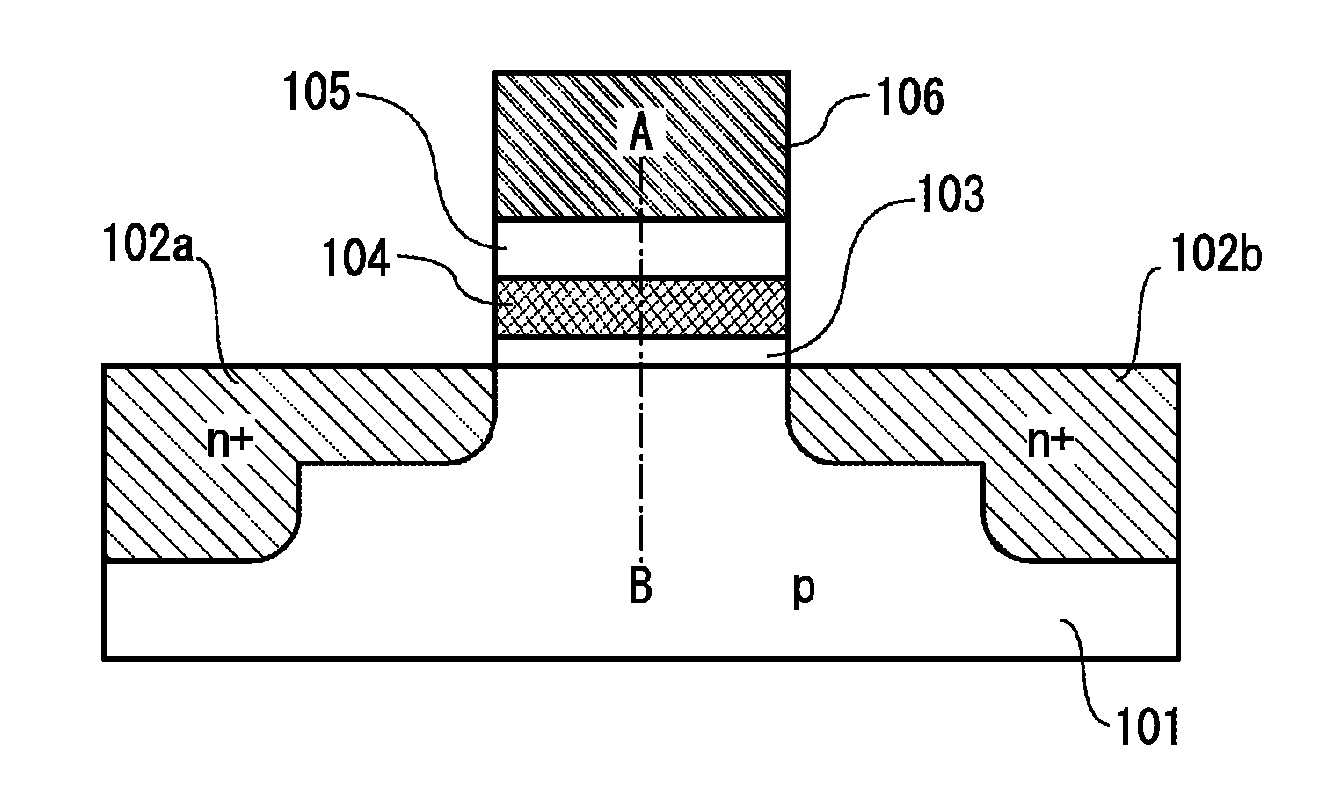
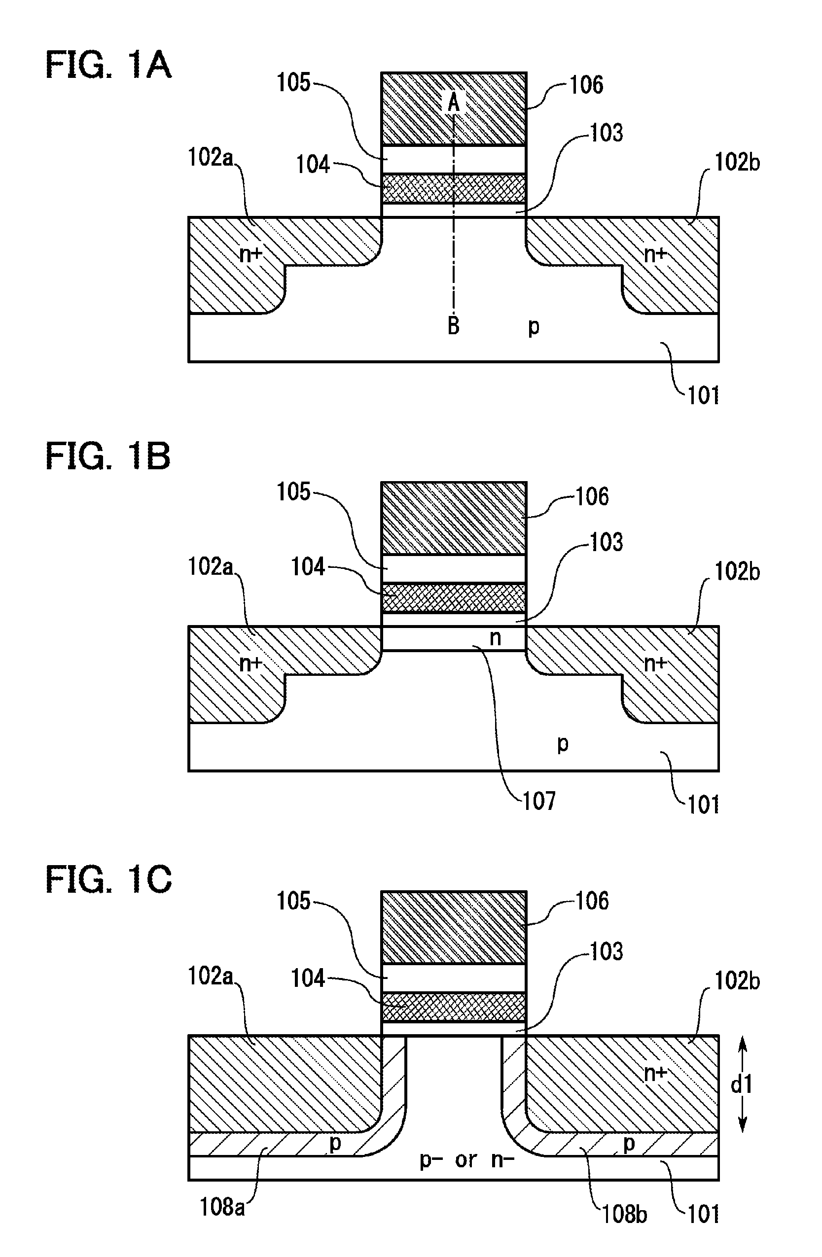
[0036]FIG. 1A illustrates an example of an FG memory device in this embodiment. Here, a schematic cross-sectional view of a transistor in a channel direction is illustrated. The transistor includes a floating gate 104 including a high-work-function compound semiconductor having a thickness of greater than or equal to 5 nm and less than or equal to 100 nm over a substrate 101 of p-type single crystal silicon, and includes a floating gate insulating film 103 with an appropriate thickness between the floating gate 104 and the substrate 101.
[0037]Note that for the substrate 101, a semiconductor material such as germanium, gallium arsenide, or gallium antimonide which has an electron affinity of 3.5 eV to 4.5 eV and a band gap of less than or equal to 1.5 eV can be used other than silicon.
[0038]The width of the floating gate 104, which is important in determining the channel length of the transistor, is set to less than or equal to 50 nm, preferably less than or equal to 20...
embodiment 2
[Embodiment 2]
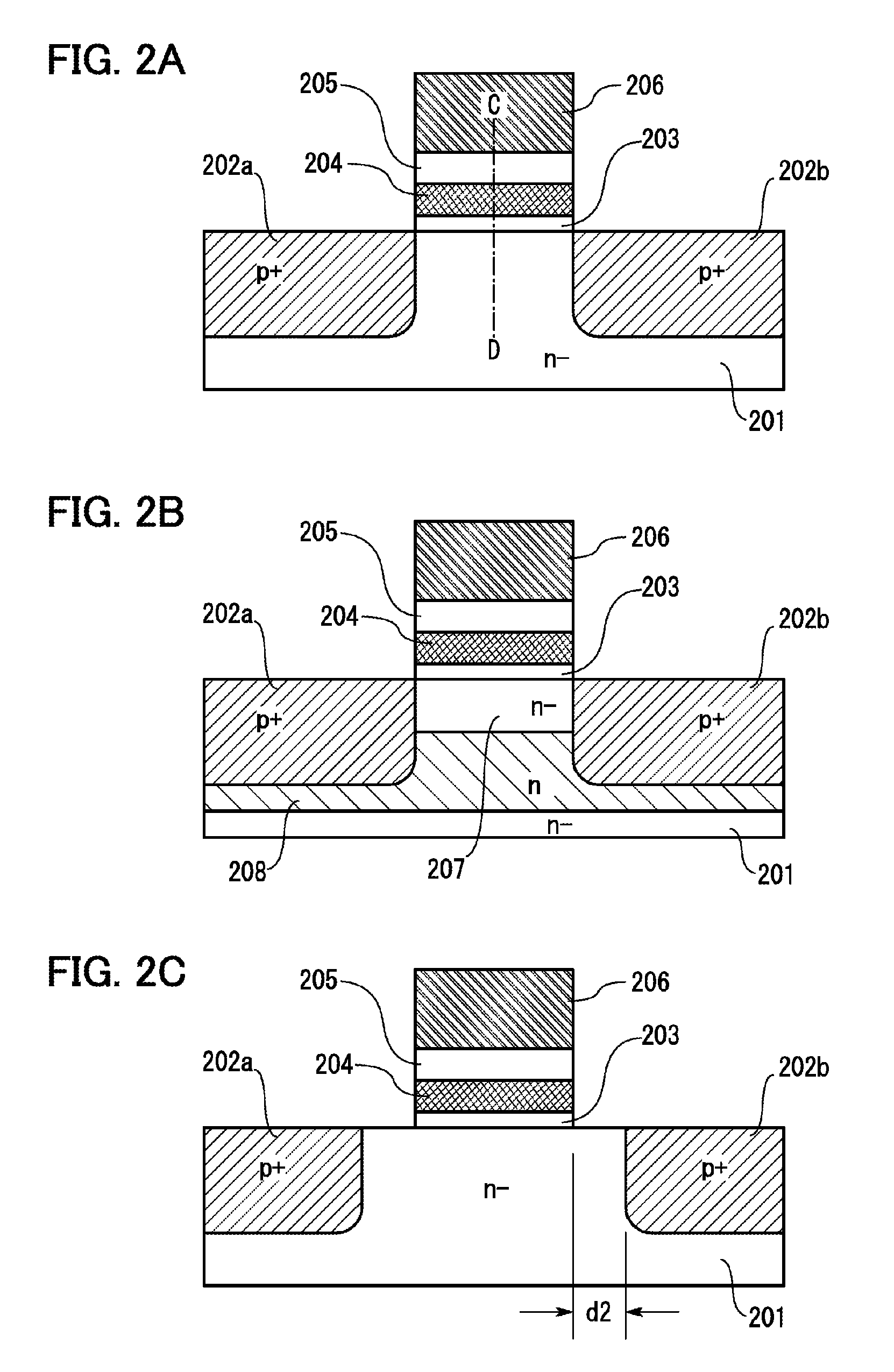
[0059]FIG. 2A illustrates an example of an FG memory device of this embodiment. Note that Embodiment 1 can be referred to for part of descriptions. Here, a schematic cross-sectional view of a transistor in a channel direction is illustrated. The transistor includes a floating gate 204 formed using a high-work-function compound semiconductor having a thickness of greater than or equal to 5 nm and less than or equal to 100 nm over an n-type single crystal silicon substrate 201, and includes a floating gate insulating film 203 having an appropriate thickness between the floating gate 204 and the substrate 201.
[0060]The width of the floating gate 204 is less than or equal to 50 nm, preferably less than or equal to 20 nm, more preferably less than or equal to 10 nm. Further, the thickness of the floating gate insulating film 203 is preferably set to 2 nm to 4 nm.
[0061]The substrate 201 is doped with p-type impurities to form a source 202a and a drain 202b. A control gate 20...
embodiment 3
[Embodiment 3]
[0065]An example of a method for manufacturing an FG memory device having both characteristics of the FG memory devices illustrated in FIGS. 2B and 2C will be described with reference to FIGS. 3A to 3C. Many steps can be performed in accordance with known semiconductor techniques; therefore, as for the details, the known techniques can be used as a reference.
[0066]First, a portion of the n-type high-resistance single crystal silicon substrate 201 (the impurity concentration is 1×1013 cm−3 to 1×1017 cm−3) to the depth of 10 nm to 200 nm is doped with n-type impurities to form the n-type region 208. As an n-type impurity element, an element which can control the depth precisely, such as arsenic, is used, and the impurity concentration may be 1×1018 cm−3 to 1×1020 cm−3. As a result, the weak n-type region 207 (having the same impurity concentration as the substrate 201) is formed in a shallow portion in the vicinity of the surface of the substrate.
[0067]Alternatively, the...
PUM
 Abstract
Description
Claims
Application Information
 - R&D
- Intellectual Property
- Life Sciences
- Materials
- Tech Scout
- Unparalleled Data Quality
- Higher Quality Content
- 60% Fewer Hallucinations
Browse by: Latest US Patents, China's latest patents, Technical Efficacy Thesaurus, Application Domain, Technology Topic, Popular Technical Reports.
© 2025 PatSnap. All rights reserved.Legal|Privacy policy|Modern Slavery Act Transparency Statement|Sitemap|About US| Contact US: help@patsnap.com


