
Anti-reflection film

a technology of anti-reflection film and anti-static properties, applied in the field of anti-reflection film, can solve the problems of dry coating method unsuitability for mass production, problem of dirtiness, and decrease in display quality, and achieve the effects of sufficient anti-reflection properties, excellent contrast, and sufficient anti-static properties

Active Publication Date: 2013-10-29
TOPPAN PRINTING CO LTD
View PDF20 Cites 0 Cited by
  • Summary
  • Abstract
  • Description
  • Claims
  • Application Information

AI Technical Summary

Benefits of technology

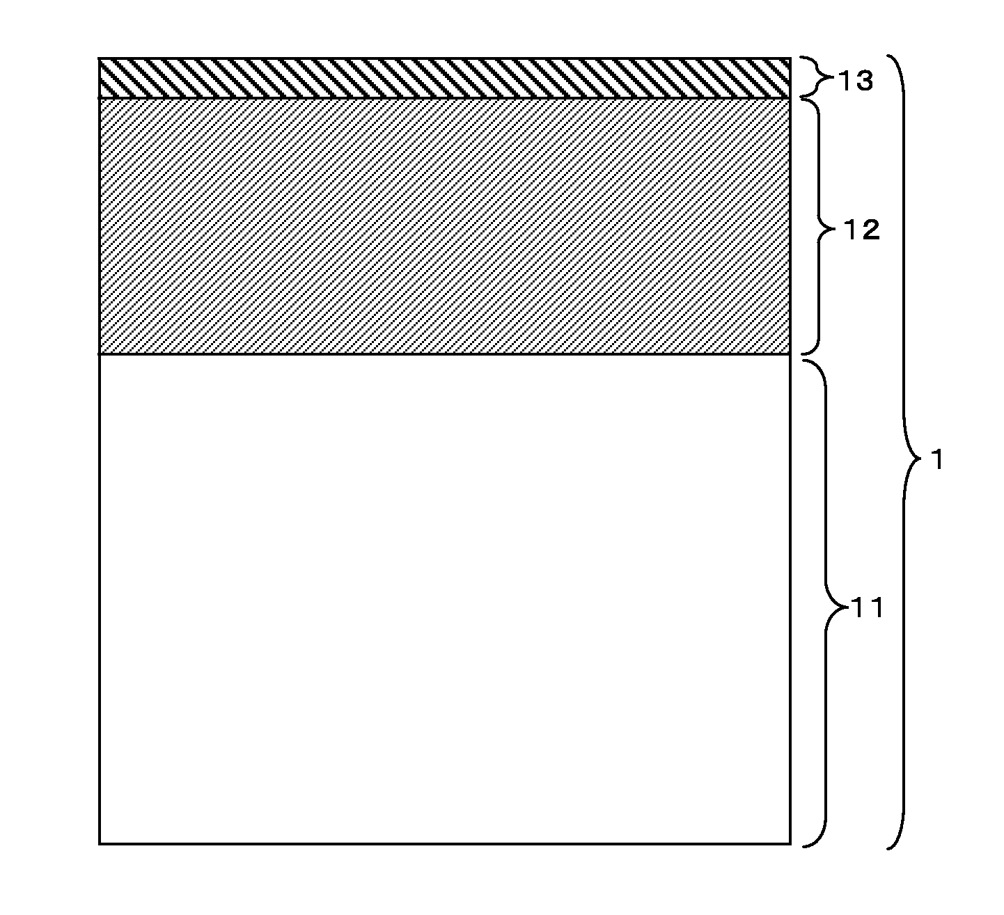
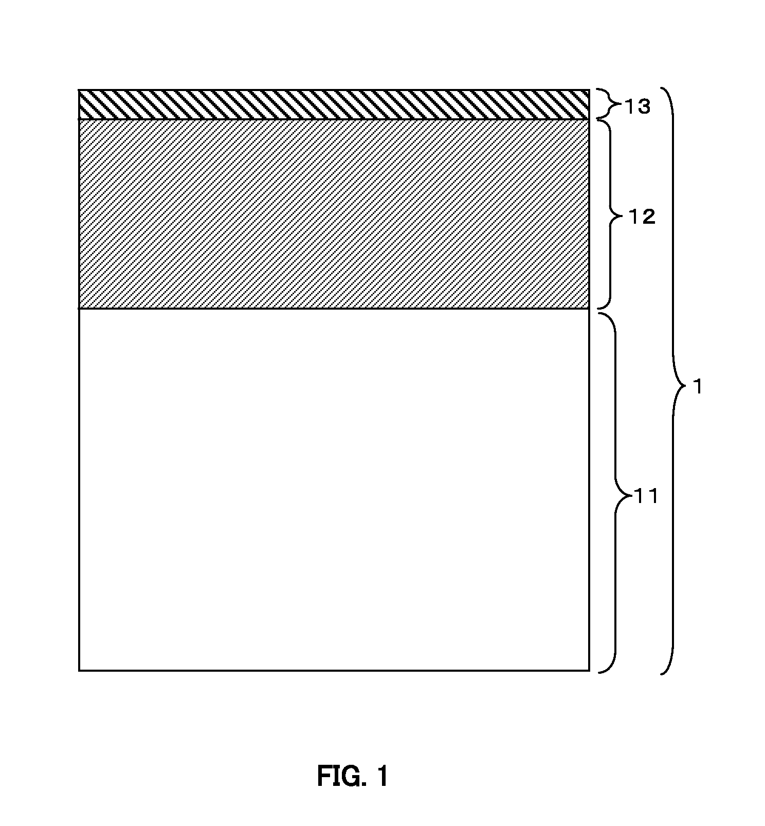
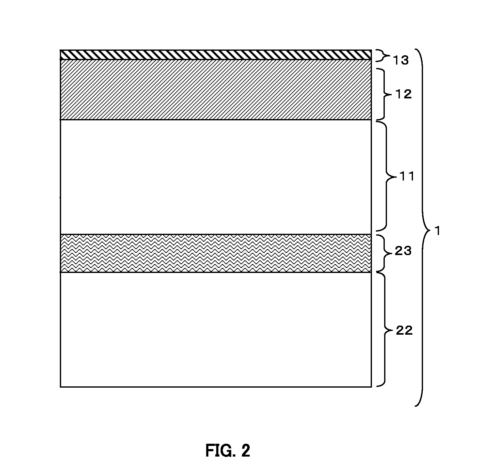
[0021]The present invention provides an anti-reflection film having a transparent substrate, an antistatic hard coat layer in which a conductive material is added to a hard coat layer, and a low refractive index layer in order, and further not only having a sufficient anti-reflection function and sufficient antistatic function but also capability of being arranged on a transmissive LCD surface to provide the LCD with excellent contrast in a bright place and excellent contrast in a dark place.
[0031]According to the present invention, it is possible to obtain an anti-reflection film which provides not only sufficient anti-reflection properties and sufficient antistatic properties but also excellent contrast in a bright place and excellent contrast in a dark place when applied on a surface of a display device, especially a transmissive LCD.

Problems solved by technology

The external light incident to a display surface is regularly reflected and causes a decrease in display quality because the reflected image overlaps and disturbs the display's image.
Although the dry coating method as a forming method of the anti-reflection layer provides capability of precisely controlling each thickness of low refractive index layers and high refractive index layers, the dry coating method has a problem of unsuitability for mass production because of low productivity of the coating process under a vacuum condition.
However, the hard coat layer which is obtained by curing an acrylic material has a high level of insulation properties and is liable to be charged resulting in an occurrence of a problem of dirtiness due to dust attachment to a surface of the anti-reflection film in which the hard coat layer is formed.
An anti-reflection film in which a conductive material is added to the hard coat layer, however, has a problem of insufficient contrast due to a decrease in luminance when displaying a white image (this type of luminance may be hereinafter referred to as “white luminance”) because an addition of the conductive material causes low visible light transmittance of the anti-reflection film.
In addition, a transmissive LCD has a problem of low contrast in a dark place caused by an insufficiently-reduced luminance when displaying a black image (“luminance when displaying a black image” may be hereinafter referred to as “black luminance”) due to a phenomenon of so-called light leakage because it is difficult to reduce orthogonal transmittance of a polarizing plate to zero.
The anti-reflection function and improvement of the visible light transmittance of the LCD, however, bring about an increase of light leakage when displaying a black image and particularly causes a problem of a fall in contrast in the dark place due to a high black luminance.

Method used


Image

  • Anti-reflection film
  • Anti-reflection film
  • Anti-reflection film

Examples


example

Example 1

[0127]An 80 μm-thick triacetyl cellulose film was used as the transparent substrate.

[0128]A polarizing plate in which an iodine-added elongated polyvinyl alcohol as the polarizing layer was interposed between two 80 μm-thick triacetyl cellulose films (first transparent substrate and second transparent substrate) was prepared.

[0129]16.7 parts by weight of Baytron P CH 8000 (dispersion liquid, solid content: 3 wt %, made by H. C. Starck GmbH) as the electron-conducting polymer, 10 parts by weight of dipentaerythritol hexaacrylate (DPHA), 10 parts by weight of pentaerythritol tetraacrylate (PETA) and 30 parts by weight of urethane acrylate UA-306T (made by Kyoeisha Chemical Co., Ltd.) as the ionizing radiation curable material, 2.5 parts by weight of Irgacure 184 (made by Ciba Japan KK) as the photopolymerization initiator, and 33.3 parts by weight of a solvent mixture (1:1 weight ratio) of methyl ethyl ketone and butyl acetate as the solvent were mixed together to prepare the...

example 2

[0132]Similar to Example 1, an 80 μm-thick tri acetyl cellulose film was used as the transparent substrate.

[0133]Similar to Example 1, a polarizing plate in which an iodine-added elongated polyvinyl alcohol as the polarizing layer was interposed between two 80 μm-thick tri acetyl cellulose films (first transparent substrate and second transparent substrate) was used.

[0134]6.7 parts by weight of dispersion liquid of antimony doped tin oxide (ATO) particles (average particle diameter: 8 nm, solid content: 30 wt %) as the electron-conducting inorganic particles, 9.6 parts by weight of dipentaerythritol hexaacrylate (DPHA), 9.6 parts by weight of pentaerythritol tetraacrylate (FETA) and 28.8 parts by weight of urethane acrylate UA-306T (made by Kyoeisha Chemical Co., Ltd.) as the ionizing radiation curable material, 2.5 parts by weight of Irgacure 184 (made by Ciba Japan KK) as the photopolymerization initiator, and 45.3 parts by weight of a solvent mixture (1:1 weight ratio) of methyl ...

example 3

[0137]Similar to Example 1, an 80 μm-thick tri acetyl cellulose film was used as the transparent substrate.

[0138]Similar to Example 1, a polarizing plate in which an iodine-added elongated polyvinyl alcohol as the polarizing layer was interposed between two 80 μm-thick triacetyl cellulose films (first and second transparent substrate) was used.

[0139]16.7 parts by weight of Baytron P CH 8000 (dispersion liquid, solid content: 3 wt %, made by H. C. Starck GmbH) as the electron conducting polymer, 6.7 parts by weight of a dispersion liquid of antimony doped tin oxide (ATO) particles (average particle diameter: 8 nm, solid content: 30 wt %) as the electron-conducting inorganic particles, 9.6 parts by weight of dipentaerythritol hexaacrylate (DPHA), 9.6 parts by weight of pentaerythritol tetraacrylate (PETA) and 28.8 parts by weight of urethane acrylate UA-306T (made by Kyoeisha Chemical Co., Ltd.) as the ionizing radiation curable material, 2.5 parts by weight of Irgacure 184 (made by C...


PUM

PropertyMeasurementUnit
wavelengthsaaaaaaaaaa

Abstract

The present invention provides an anti-reflection film which provides not only sufficient anti-reflection properties and antistatic properties but also excellent contrast in a bright place and excellent contrast in a dark place especially applied on a surface of a transmissive LCD. The anti-reflection film has an antistatic hard coat layer and a low refractive index layer in order on at least one surface of a transparent substrate, average luminous reflectance in the range of 0.5-1.5% on a surface of the low refractive index layer side, haze equal to or less than 0.5%, parallel light transmittance in the range of 94.0-96.5%, and an absorption loss in average luminous transmittance in the range of 0.5-3.0%.

Description

[0001]This application is a continuation of International Application No. PCT / JP2009 / 066813, filed Sep. 30, 2008, which is incorporated herein by reference in its entirety.BACKGROUND OF THE INVENTION[0002]1. Field of the Invention[0003]The present invention relates to an anti-reflection film which is used in order to prevent external light from reflecting on a surface of a window or a display etc. Specifically, the present invention relates to an anti-reflection film which is arranged on a surface of a display device such as a liquid crystal display (LCD), CRT display, organic electroluminescence display (ELD), plasma display (PDP), surface-conduction electron-emitter display (SED) and field emission display (FED) etc. In particular, the present invention relates to an anti-reflection film which is arranged on a surface of a transmissive LCD.[0004]2. Description of the Related Art[0005]In general, displays are used under an environment of incidence of external light. The external li...

Claims


Application Information

Patent Timeline
Patent Type & Authority Patents(United States)
IPC IPC(8): G02F1/1335
CPCB32B23/08B32B23/20B32B27/06B32B27/18B32B27/30G02B1/111G02B1/105G02B5/3033G02F1/133502Y10T428/31663G02B1/16G02B1/113
Inventor YOSHIHARA, TOSHIAKIHIGASHIKAWA, EIICHISHIBAYAMA, NAOYUKI
Owner TOPPAN PRINTING CO LTD
Learn More