
Seat construction

a seat and seat technology, applied in the direction of movable seats, chairs, pedestrian/occupant safety arrangements, etc., to achieve the effect of light weight and increased intensity

Inactive Publication Date: 2007-12-04
DELTA TOOLING CO LTD
View PDF9 Cites 26 Cited by
  • Summary
  • Abstract
  • Description
  • Claims
  • Application Information

AI Technical Summary

Benefits of technology

The seat structure achieves a significantly higher intensity of backward moment, improving impact resistance while maintaining a lightweight design, effectively restraining the seat back and human body during collisions, and providing both vibration absorption and high-impact resistance.

Problems solved by technology

However, various spring mechanisms used here are to serve mainly as a vibration absorptive function and do not positively possess a function to serve as a high-impact material capable of resisting against impact force from front or back equal to or stronger than that prescribed due to a head-on or rear-end collision.

Method used


Image

  • Seat construction
  • Seat construction
  • Seat construction

Examples


Embodiment Construction

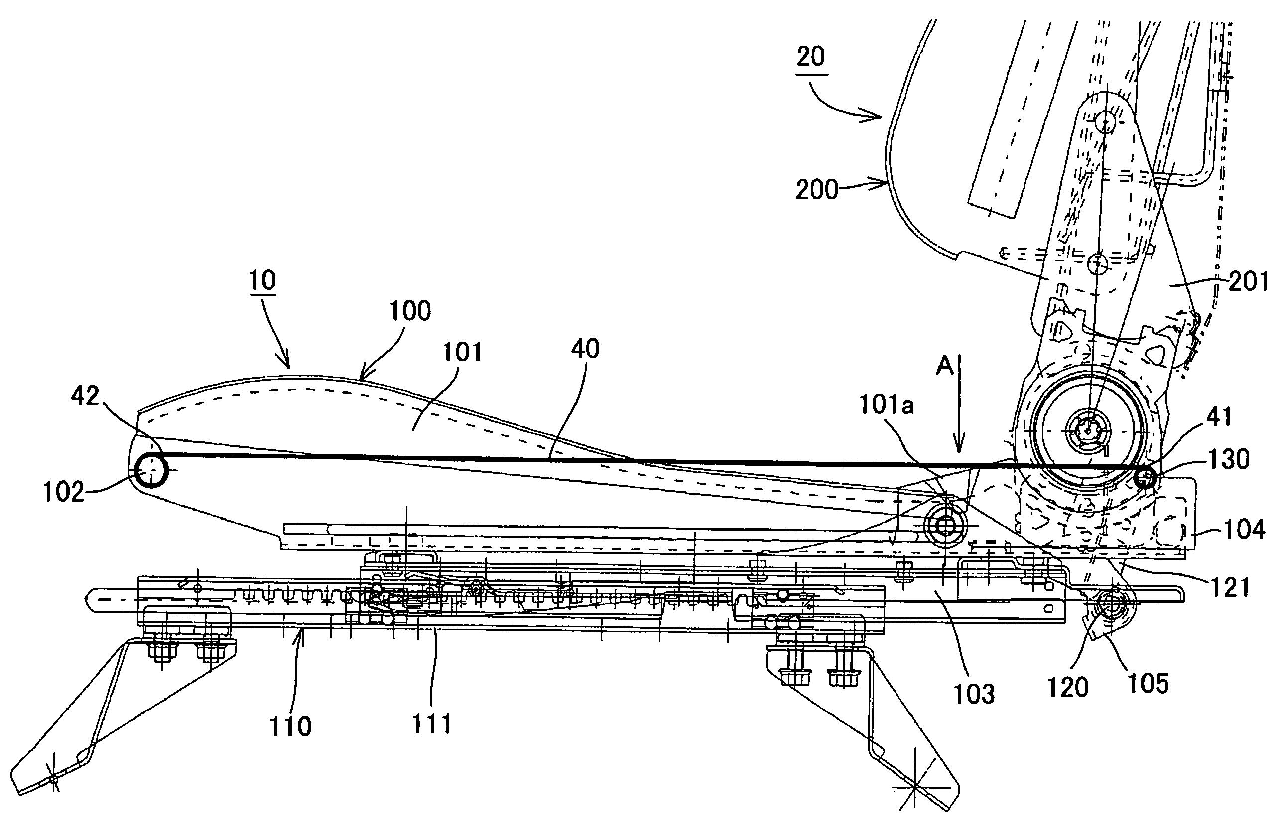
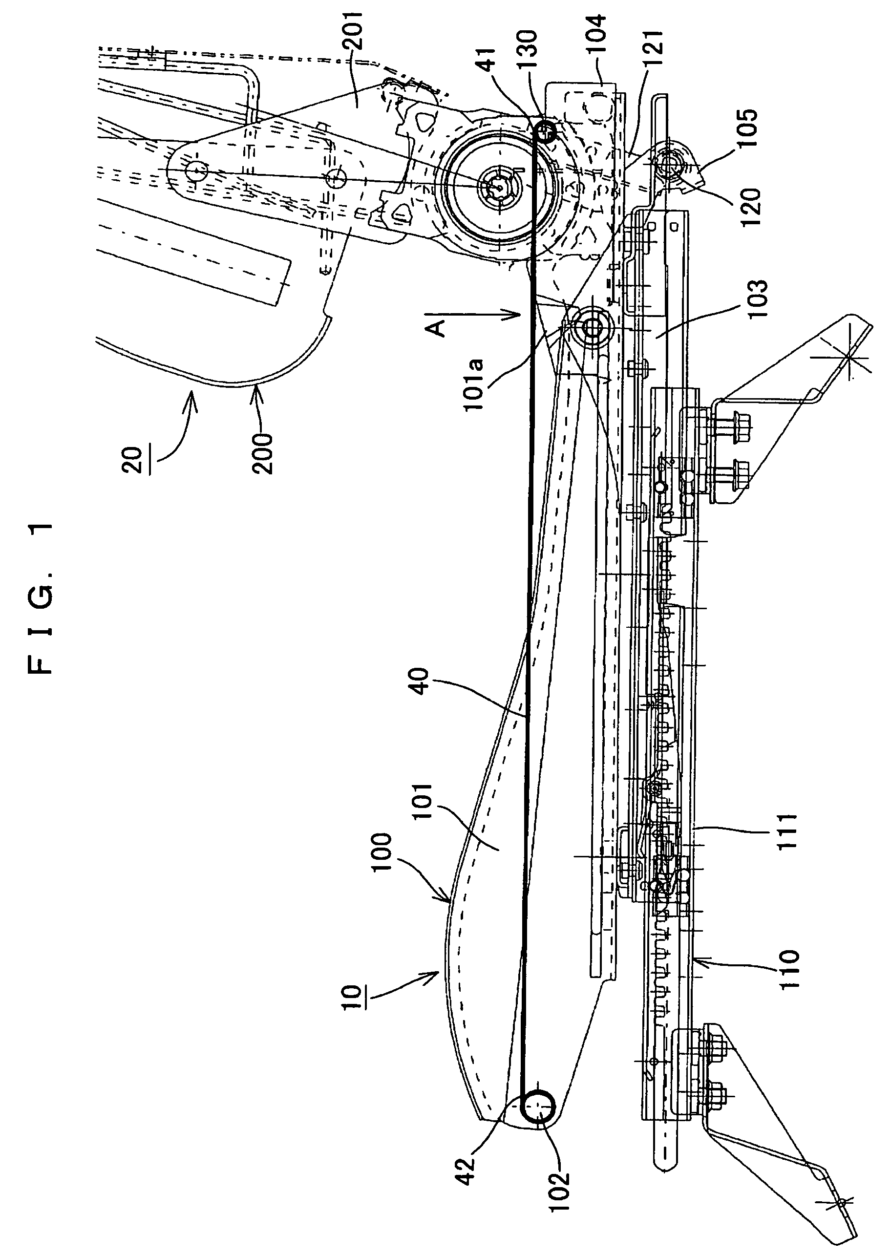
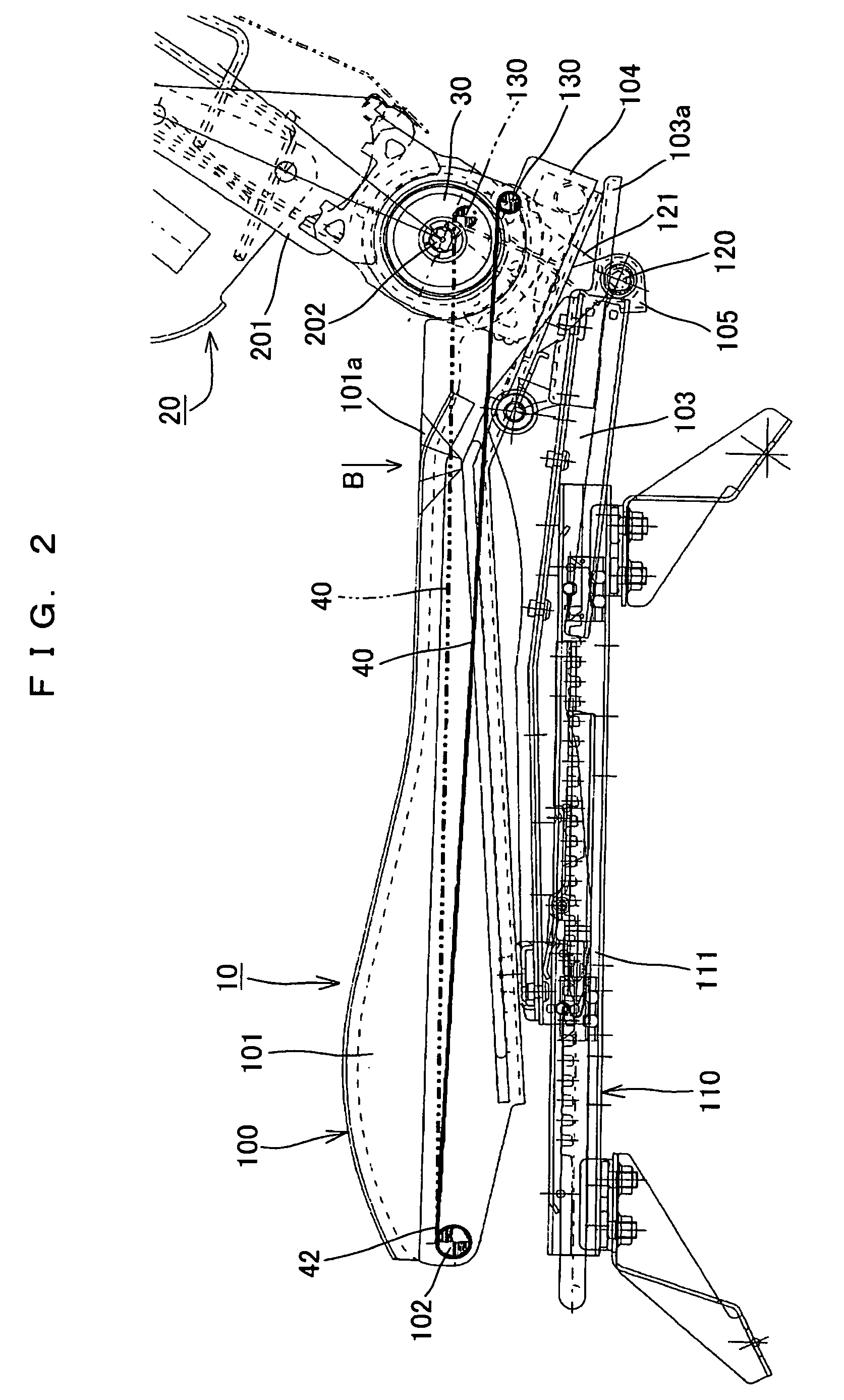
[0025]The present invention will be explained in more detail based on embodiments shown in the drawings. FIGS. 1 and 2 are views showing a main portion of a seat structure relating to an embodiment of the present invention. As shown in these drawings, a seat cushion 10 and a seat back 20 forming the seat structure of the present embodiment include a cushion frame 100 and a back frame 200 respectively.

[0026]The cushion frame 100 is formed with a plurality of frame members such as side frames 101 disposed apart from and opposite to each other in the width direction, a front edge frame 102 disposed between both front ends of the side frames 101 and the like so as to form nearly a square or the shape of a letter U seen from the top as a whole. To the side frame 101, a fixing bracket 103 is fixed along the bottom edge thereof and the side frame 101 is slidably supported by a rail 111 which forms a slide adjuster 110 via the fixing bracket 103.

[0027]The side frame 101 which is one of the ...


PUM


Abstract

A flat spring member (40) mainly serving as a vibration absorptive function at a normal use is engaged with a supporting frame member (130) which displaces backward along with deformation of a seat back (20) by backward moment applied to the seat back (20), and the other end is engaged with a front edge frame (102) disposed in the vicinity of the front edge of a cushion frame. Therefore, when an impact force from front or back equal to or more than that prescribed is applied, the flat spring member (40) increases in tension by backward moment applied to the seat back (20), and serves as a function to increase again the intensity of the backward moment of the seat back (20), which was once lowered by deformation of the side frame (101) of the cushion frame.

Description

FIELD OF THE INVENTION[0001]The present invention relates to a seat structure, more in detail, to a seat structure suitable for transportation machines such as a plane, a train, a ship, a fork lift, an automobile and the like, or for various chairs and a wheel chair used inside or outside of a building.BACKGROUND OF THE INVENTION[0002]In a seat used in a plane, a train, a ship, an automobile and the like, a seat back is required to be tilted not more than necessity when a large impact force is applied upon a head-on collision or a rear-end collision. When a seat back tilts too deep, a passenger on a back seat may be injured. It is also conceivable that the leg is caught in a steering, which may cause a risk to receive an injury by a load on the waist or the like or receive an injury on the head by baggage put on the back seat. Therefore, it is required to restrain a tilt of a seat back to restrain displacement of the human body by pushing the passenger's back to a cushioning materia...

Claims


Application Information

Patent Timeline
Patent Type & Authority Patents(United States)
IPC IPC(8): B60N2/42A47C7/14B60N2/06B60N2/427B60N2/70
CPCA47C7/14B60N2/7011B60N2/427B60N2/06B60N2/22
Inventor FUJITA, ETSUNORICHIZUKA, KAZUYOSHIKAWASAKI, SEIJITAKATA, YASUHIDE
Owner DELTA TOOLING CO LTD
Learn More