
Control method for screw of injection molding machine

a technology of injection molding machine and control method, which is applied in the direction of auxillary shaping apparatus, manufacturing tools, ceramic shaping apparatus, etc., can solve the problems of shortening the storage time of resin, reducing the reliability of products, and oxidation or carbonation of resin due to decomposition of polymer, so as to reduce the variation in pressure and reduce the variation in the weight of injection products.

Active Publication Date: 2013-10-29
LS MTRON LTD
View PDF9 Cites 0 Cited by
  • Summary
  • Abstract
  • Description
  • Claims
  • Application Information

AI Technical Summary

Benefits of technology

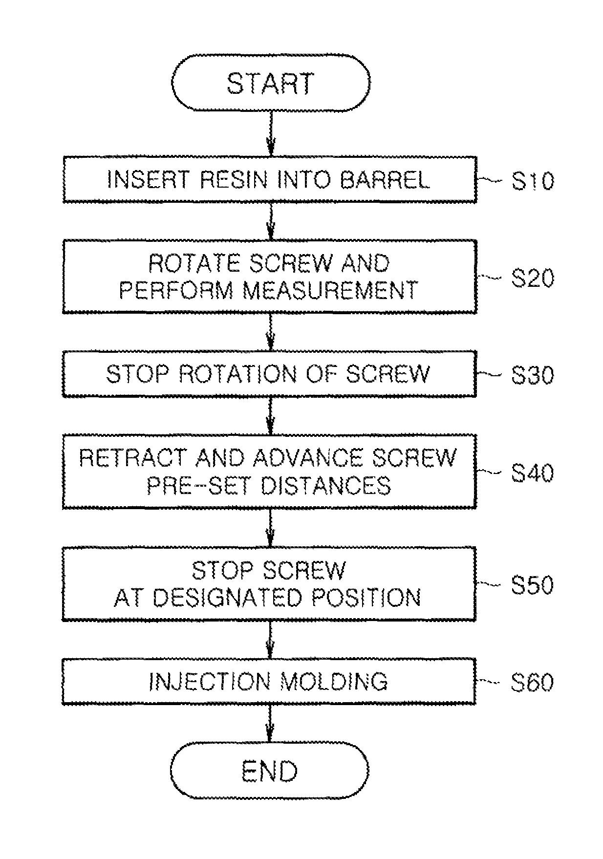
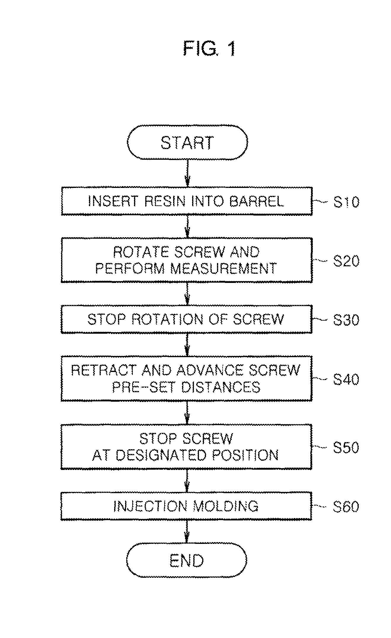
[0013]The present disclosure is directed to providing a screw control method of an injection molding machine capable of, before injection molding of a resin that is melted and compressed inside an injection molding machine, reducing variations in pressure depending on the position of the melted resin by retracting and advancing a screw predetermined distances, and then advancing the screw to inject the melted resin, thereby reducing variations in the weights of injection products.

Problems solved by technology

If a resin congestion occurs in the screw head part of the injection device, the detention time of the resin is lengthened, and oxidation or carbonation of the resin due to decomposition of polymer may occur.
When injection products are continuously made by injecting the melted resin in which pressure is not uniformly distributed, the weights of the injection products vary, resulting in degradation of reliability of products.

Method used


Image

  • Control method for screw of injection molding machine
  • Control method for screw of injection molding machine
  • Control method for screw of injection molding machine

Examples


Embodiment Construction

[0021]Exemplary embodiments now will be described more fully hereinafter with reference to the accompanying drawings, in which exemplary embodiments are shown. The present disclosure may, however, be embodied in many different forms and should not be construed as limited to the exemplary embodiments set forth therein. Rather, these exemplary embodiments are provided so that the present disclosure will be thorough and complete, and will fully convey the scope of the present disclosure to those skilled in the art. In the description, details of well-known features and techniques may be omitted to avoid unnecessarily obscuring the presented embodiments.

[0022]The terminology used herein is for the purpose of describing particular embodiments only and is not intended to be limiting of the present disclosure. As used herein, the singular forms “a”, “an” and “the” are intended to include the plural forms as well, unless the context clearly indicates otherwise. Furthermore, the use of the t...


PUM

PropertyMeasurementUnit
meltingaaaaaaaaaa
pre-set distanceaaaaaaaaaa
stroke distanceaaaaaaaaaa

Abstract

A screw control method of an injection molding machine including a barrel into which a resin is inserted, a screw installed to be rotatable inside the barrel, a check ring on a rear side of a screw head, and a controller controlling operations of the screw includes: measuring an amount of resin to be injected and inserting the resin into the barrel until the amount of resin reaches the measured amount of resin; completing the measurement while melting the inserted resin through rotation of the screw; stopping the rotation of the screw after completing the measurement of the resin; after retracting the screw of which the rotation is stopped a pre-set distance, advancing the screw a pre-set distance; and performing injection molding of the melted resin by advancing the screw, where the rotation, advance, and retraction operations of the screw are made according to control signals of the controller.

Description

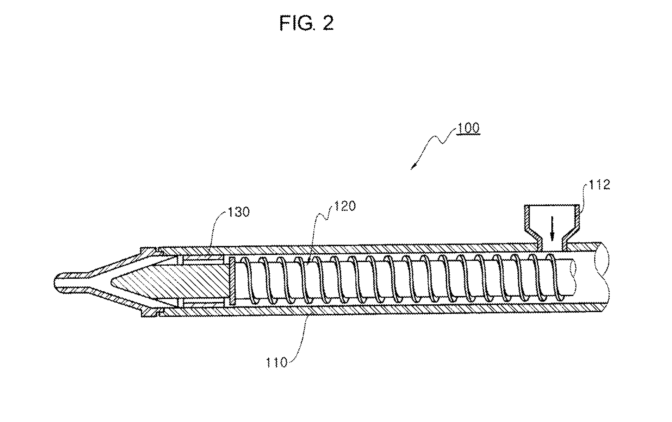
CROSS-REFERENCE TO RELATED APPLICATION[0001]This application claims priority to Korean Patent Application No. 10-2011-0008288, filed on Jan. 27, 2011, and all the benefits accruing therefrom under 35 U.S.C. §119, the contents of which in its entirety are herein incorporated by reference.BACKGROUND[0002]1. Field[0003]The present disclosure relates to a screw control method of an injection molding machine, and more particularly, to a screw control method capable of controlling the advance and retraction of a screw so as to uniformly distribute the internal pressure of a melted resin, thereby reducing variations in the weight of an injection product injected from the screw.[0004]2. Description of the Related Art[0005]In general, an injection apparatus is an apparatus for injecting a resin into a mold manufactured to be suitable for the shape of a product to be formed, and is an apparatus that melts resin granules in a solid state using mechanical energy generated by rotation of a screw...

Claims


Application Information

Patent Timeline
Patent Type & Authority Patents(United States)
IPC IPC(8): B29C45/50B29C45/76B29C48/92
CPCB29C45/50B29C45/52B29C47/92B29C2045/5096B29C2945/76107B29C2945/7618B29C2945/76367B29C2945/76605B29C45/77B29C45/48
Inventor HYUN, CHANG HOON
Owner LS MTRON LTD
Learn More