
Radiation source and method for the generation of X-radiation

a radiation source and x-ray technology, applied in the direction of x-ray tube electrodes, x-ray tubes with very high current, diagnostics, etc., can solve the problems of high thermal load acting on the interaction zone, difficult dissipation of heat generated in the focal spot of a solid body, and limited achievable output power of x-ray radiation, etc., to achieve high reliability of radiation sources

Active Publication Date: 2013-10-22
FRAUNHOFER GESELLSCHAFT ZUR FOERDERUNG DER ANGEWANDTEN FORSCHUNG EV
View PDF20 Cites 9 Cited by
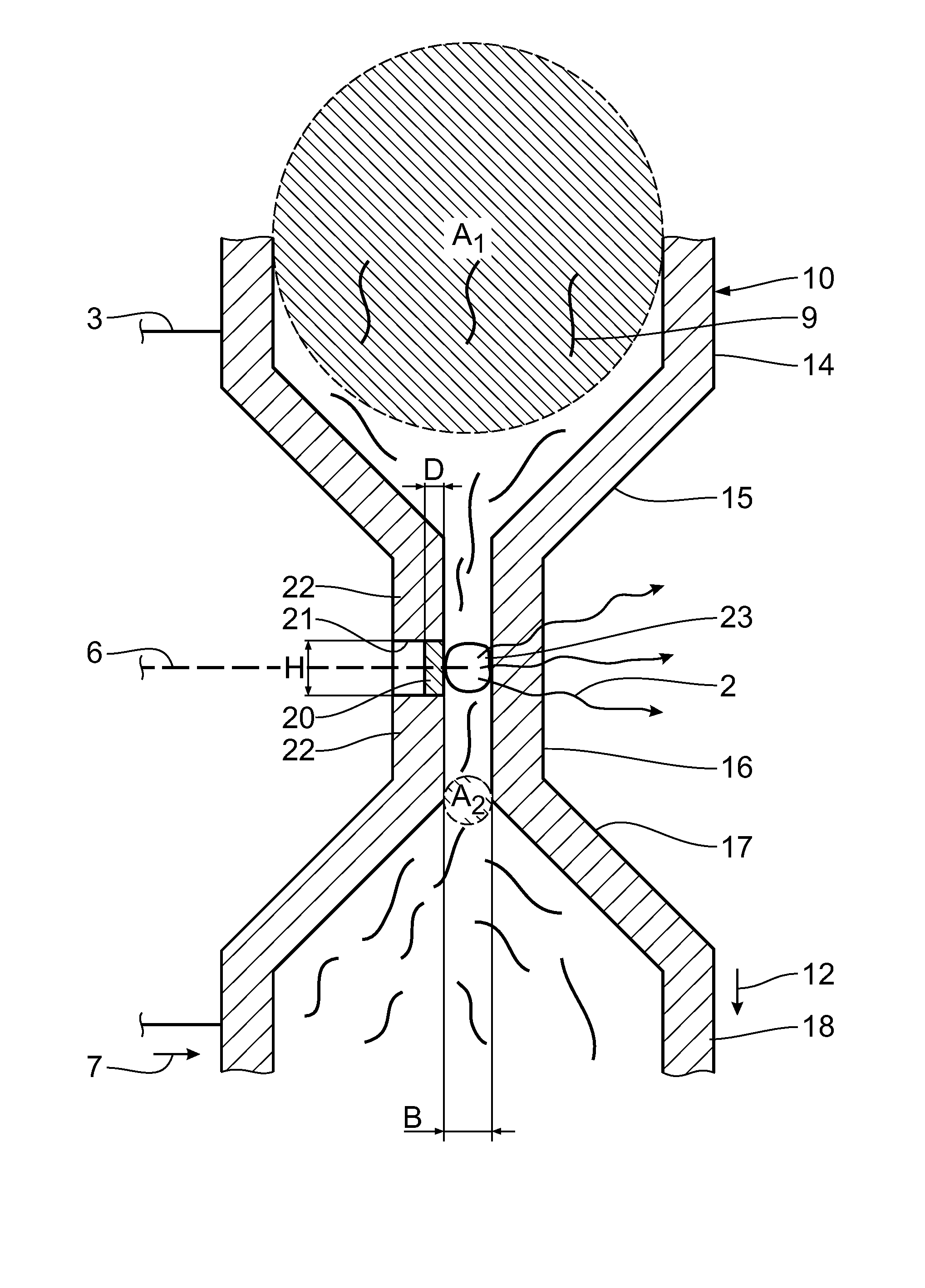
  • Summary
  • Abstract
  • Description
  • Claims
  • Application Information

AI Technical Summary

Benefits of technology

[0005]It is therefore the object of the invention to provide a radiation source for the generation of high-energy X-radiation which allows large amounts of heat to be dissipated from the interaction zone while ensuring full functionality and high reliability of the radiation source.
[0006]This object is achieved according to the invention by a radiation source for the generation of X-radiation, the radiation source comprising an evacuated chamber; an electron beam generation unit for the generation of an electron beam extending in the chamber in an electron beam direction; a target unit, the target unit comprising a liquid line with a liquid arranged therein, the liquid line extending transversely to the electron beam direction, with an interaction zone for the generation of X-radiation being generable by interaction of the electron beam and the liquid, with the liquid being completely surrounded by the liquid line in the direction of the chamber, and with at least a portion of the liquid line being permeable to the electron beam in such a way that the interaction zone is generable inside the liquid line. As the liquid acting as X-ray target is completely surrounded by the liquid line in the direction of the evacuable chamber, the liquid is entirely separated from the chamber, thus preventing liquid from escaping the liquid line and from depositing in the chamber. Heat dissipation from the interaction zone by means of the liquid jet is not impaired by the liquid line. At least the portion of the liquid line through which the electrons enter the liquid line is substantially permeable or transparent to the electron beam to keep the loss of kinetic energy of the electrons in the electron beam as low as possible when entering the liquid line. The permeable design prevents the electrons from interacting with the liquid line, allowing the electron beam to interact with the liquid in order to form the interaction zone without any loss of energy in the liquid line. Due to the liquid acting as X-ray target, the inventive radiation source thus allows a good dissipation of heat from the interaction zone while simultaneously preventing the escape of liquid from the liquid line to avoid an impaired functionality and reliability of the radiation source. If required, the electron beam generation unit may be operated at higher acceleration voltage, in particular at more than 500 kV, in particular at more than 1 MV, and in particular at more than 3 MV, causing a corresponding high-energy X-radiation to be generated which is preferably emitted in the electron beam direction. Suitable liquids are liquid metals such as mercury or liquids containing metal microparticles.
[0007]A development of the target unit where the target unit is designed such that the X-radiation is emissible substantially in the electron beam direction ensures easy generation of high-energy X-radiation. The liquid provided by means of the target unit serves as so-called transmission X-ray target. The generated X-radiation is substantially emitted in the electron beam direction. To this end, the side of the liquid line opposite to the electron beam permeable portion is X-ray permeable or transparent, allowing the X-radiation to exit the liquid line in the electron beam direction substantially without any loss of energy. When the acceleration voltage or energy of the electrons increases, the intensity relationship of X-radiation generated in the electron beam direction compared to X-radiation generated opposite to the electron beam direction increases as well. At higher acceleration voltages from approximately 1 MV, or high electron energies from approximately 1 MeV, the X-radiation is generated substantially in the electron beam direction, which is taken advantage of in the target unit. The liquid arranged in the liquid line thus forms a transmission X-ray target. The generation efficiency for high-energy X-radiation is much higher in the inventive transmission X-ray target than in a reflection X-ray target where the X-radiation is substantially generated opposite to the electron beam direction. The electron beam generation unit is therefore operable at an acceleration voltage of at least 500 kV, in particular of at least 1 MV, and in particular of at least 3 MV.

Problems solved by technology

In conventional X-radiation sources, the X-ray target is a solid body; under electron beam bombardment, a high temperature increase can be observed in the interaction zone, the so-called focal spot, of the solid body, which results in high thermal loads acting on the interaction zone.
A dissipation of the heat generated in the focal spot of a solid body is very difficult.
The achievable output power of the X-radiation is therefore limited due to the thermal load of the X-ray target.
A drawback is that in the event of an excessive temperature increase of the liquid jet, the vapor pressure of the liquid jet may increase such that complete removal thereof is impossible, causing a part of the liquid jet to evaporate and to deposit on the internal walls of the evacuated chamber.
This impairs the functionality and reliability of the X-radiation source.

Method used


Image

  • Radiation source and method for the generation of X-radiation
  • Radiation source and method for the generation of X-radiation
  • Radiation source and method for the generation of X-radiation

Examples


Embodiment Construction

[0026]A radiation source 1 comprises an evacuated chamber 3 for the generation of high-energy X-radiation 2. An electron beam generation unit 5 is arranged at a first end 4 of the evacuated chamber 3. The electron beam generation unit 5 serves for the generation of an electron beam 6 extending along the chamber 3 in an electron beam direction 7. In order to accelerate the electrons forming the electron beam 6, the electron beam generation unit 5 is operable at a maximum acceleration voltage UB of 160 kV to 24 MV, in particular of 500 kV to 24 MV, in particular of 1 MV to 24 MV, and in particular of 3 MV to 24 MV. Alternatively, the upper limit for the acceleration voltage may amount to 18 MV. The electron beam generation unit 5 is a linear accelerator (LINAC) where the electrons are generable by thermionic emission and are accelerable in several steps in an evacuated tube, the so-called waveguide. At lower acceleration voltages UB, the electron beam generation unit 5 may alternative...


PUM


Abstract

In a radiation source and a method for the generation of X-radiation, a liquid is arranged in a liquid line, the liquid being completely surrounded by the liquid line in the direction of an evacuated chamber. A portion of the liquid line is permeable to an electron beam such that the electron beam extending through the chamber is able to enter via the liquid line so as to interact with the liquid in an interaction zone for the generation of X-radiation. The radiation source ensures a good dissipation of heat from the interaction zone and prevents liquid from entering the chamber.

Description

CROSS REFERENCE TO RELATED APPLICATIONS[0001]This application is a U.S. National Phase application of International Application PCT / EP2009 / 003784 and claims the benefit of priority under 35 U.S.C. §119 of German Patent Application DE 10 2008 026 938.7 filed Jun. 5, 2008, the entire contents of which are incorporated herein by reference.FIELD OF THE INVENTION[0002]The invention relates a radiation source for the generation of X-radiation. The invention further relates to a method for the generation of X-radiation.BACKGROUND OF THE INVENTION[0003]Non-destructive examination of objects by means of X-ray computer tomography requires the use of high-energy X-radiation sources which allow examination of objects that have high penetration lengths or high densities. In conventional X-radiation sources, the X-ray target is a solid body; under electron beam bombardment, a high temperature increase can be observed in the interaction zone, the so-called focal spot, of the solid body, which resu...

Claims


Application Information

Patent Timeline
Patent Type & Authority Patents(United States)
IPC IPC(8): G21G4/08H01J35/08H05G1/02
CPCH01J35/08H01J35/12H01J2235/082H01J35/116H01J35/13
Inventor SUKOWSKI, FRANKUHLMANN, NORMAN
Owner FRAUNHOFER GESELLSCHAFT ZUR FOERDERUNG DER ANGEWANDTEN FORSCHUNG EV
Learn More