
Micromechanical device including N-type doping for providing temperature compensation and method of designing thereof

a micromechanical device and temperature compensation technology, applied in waveguide devices, generators/motors, instruments, etc., can solve the problems of increasing energy consumption, high temperature drift of resonance frequency, and inability to provide a resonator with sufficiently low temperature drift with low cost technology, etc., to achieve the effect of temperature sensitivity

Active Publication Date: 2013-10-15
TEKNOLOGIAN TUTKIMUSKESKUS VTT
View PDF8 Cites 40 Cited by
  • Summary
  • Abstract
  • Description
  • Claims
  • Application Information

AI Technical Summary

Benefits of technology

The invention introduces a temperature compensated semiconductor structure that can manage its temperature sensitivity properties over a wide temperature range. The structure is free of p-dopants, which avoids the presence of pn-junctions in the resonator. The overall temperature drift of the semiconductor element's stiffness is 50 ppm or less on a temperature range of 300°C or wider.

Problems solved by technology

However, a problem associated with silicon based resonators is that they have a high temperature drift of the resonance frequency.
The prior art solutions include:Active compensation with a temperature sensor and related electronic control circuitry, but it has not been possible to provide a resonator with sufficiently low temperature drift with low cost technology which would be suitable for mass production applications and would compete with quartz quality.
Also, the use of a temperature compensation circuit increases the consumption of energy, which is a significant disadvantage especially in battery operated devices.
Further, the compensation circuit tends to increase electric noise in the resonator circuit.Active compensation by stabilizing the temperature of the resonator with temperature isolation and controlled warming / cooling of the resonator.
However, this solution also increases the energy consumption of the device, and makes the device complicated to produce.
The temperature compensation circuits are also slow in controlling, and cannot therefore compensate fast or large changes in ambient temperature sufficiently well.Passive compensation by addition of amorphous SiO2 exhibiting opposite sign of temperature drift to the structure.
Compensation by SiO2 leads, however, to a more complex fabrication process and resonator performance trade-offPassive compensation by heavy p-type doping, such as boron doping, compensates strongly for c44 characterized shear modes, like the Lamé mode, but less or not at all some other modes, limiting the applicability to quite special modes and excitation geometries in the case of piezoactuation.
In particular, extensional modes are not well compensated by p-type doping.
Thus, there are severe limits for the design of the resonator with respect to its volume, thickness and availability of resonance modes, for example.
For example, bulk acoustic wave modes are not effectively temperature compensated in diffusion doped resonators.

Method used


Image

  • Micromechanical device including N-type doping for providing temperature compensation and method of designing thereof
  • Micromechanical device including N-type doping for providing temperature compensation and method of designing thereof
  • Micromechanical device including N-type doping for providing temperature compensation and method of designing thereof

Examples


Embodiment Construction

[0059]In the following description, an embodiment where the distinct regions of a semiconductor resonator element comprise different n-dopant concentrations, including some variations, are described.

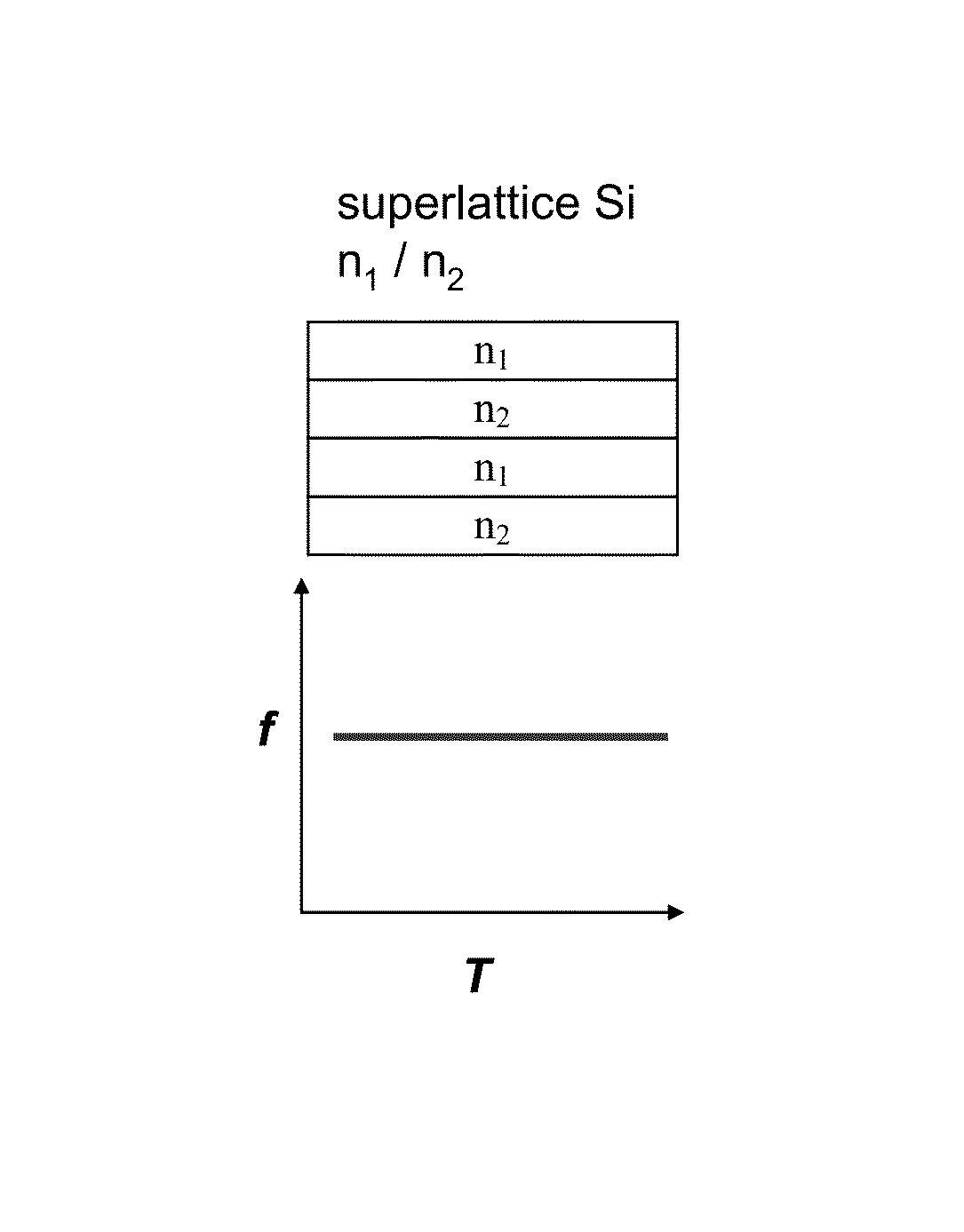
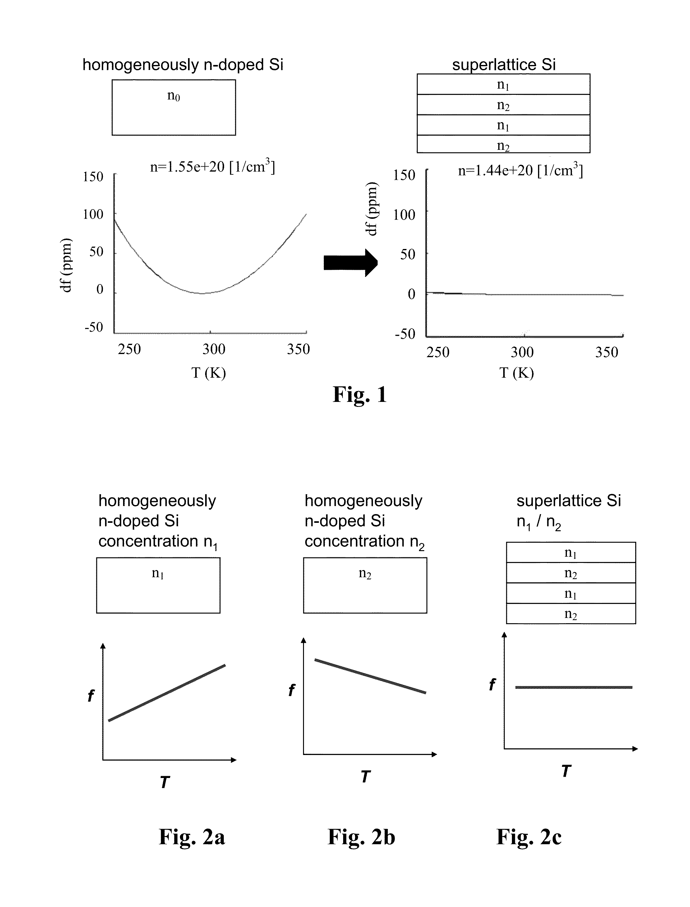
[0060]In a simplified picture, the slope of resonator frequency vs. temperature, is positive or negative slope at each temperature point, depending on the dopant concentration. These effects can be combined to cancel each other not only in some points but on a wide temperature region, if the resonator is formed of an optimized effective material which comprises arbitrary lateral and / or vertical regions with different doping levels.

[0061]These regions do not have to be discrete: concentrations within the resonator body can also vary continuously within the resonator volume, and the same cancelling effect can be obtained.

[0062]According to one embodiment, the semiconductor element is a beam. The term “beam” generally refers to elements whose in-plane aspect ratio (width vs. length) is at l...


PUM


Abstract

The invention relates to a micromechanical device comprising a semiconductor element capable of deflecting or resonating and comprising at least two regions having different material properties and drive or sense means functionally coupled to said semiconductor element. According to the invention, at least one of said regions comprises one or more n-type doping agents, and the relative volumes, doping concentrations, doping agents and / or crystal orientations of the regions being configured so that the temperature sensitivities of the generalized stiffness are opposite in sign at least at one temperature for the regions, and the overall temperature drift of the generalized stiffness of the semiconductor element is 50 ppm or less on a temperature range of 100° C. The device can be a resonator. Also a method of designing the device is disclosed.

Description

FIELD OF THE INVENTION[0001]The invention relates to temperature compensation of micromechanical devices, in particular resonators. The device and method according to the invention comprise the features of the preambles of the independent claims.BACKGROUND OF THE INVENTION[0002]Widely used quartz crystal based resonators can potentially be replaced by micromechanical, typically silicon-based resonators in many applications. Silicon resonators can be made smaller than quartz resonators and there are a plurality standard manufacturing methods for silicon resonators. However, a problem associated with silicon based resonators is that they have a high temperature drift of the resonance frequency. The drift is mainly due to the temperature dependence of the Young modulus of silicon, which causes a temperature coefficient of frequency (TCF) approx. −30 ppm / ° C. This causes the resonance frequency to fluctuate due to changes in ambient temperature. MEMS resonators made of ordinary silicon ...

Claims


Application Information

Patent Timeline
Patent Type & Authority Patents(United States)
IPC IPC(8): H03H9/24H01L21/00H03H3/013H01L29/06
CPCB81B3/0072B81B2201/0235B81B2201/0242B81B2201/0271B81C2201/0164B81C2201/0167B81C2201/0177G06F17/5045H03H9/02448H03H9/2447H03H2009/2442G06F30/30B81B3/0081H03H9/02102H03H9/02B81B3/00
Inventor PRUNNILA, MIKAJAAKKOLA, ANTTIPENSALA, TUOMAS
Owner TEKNOLOGIAN TUTKIMUSKESKUS VTT
Learn More