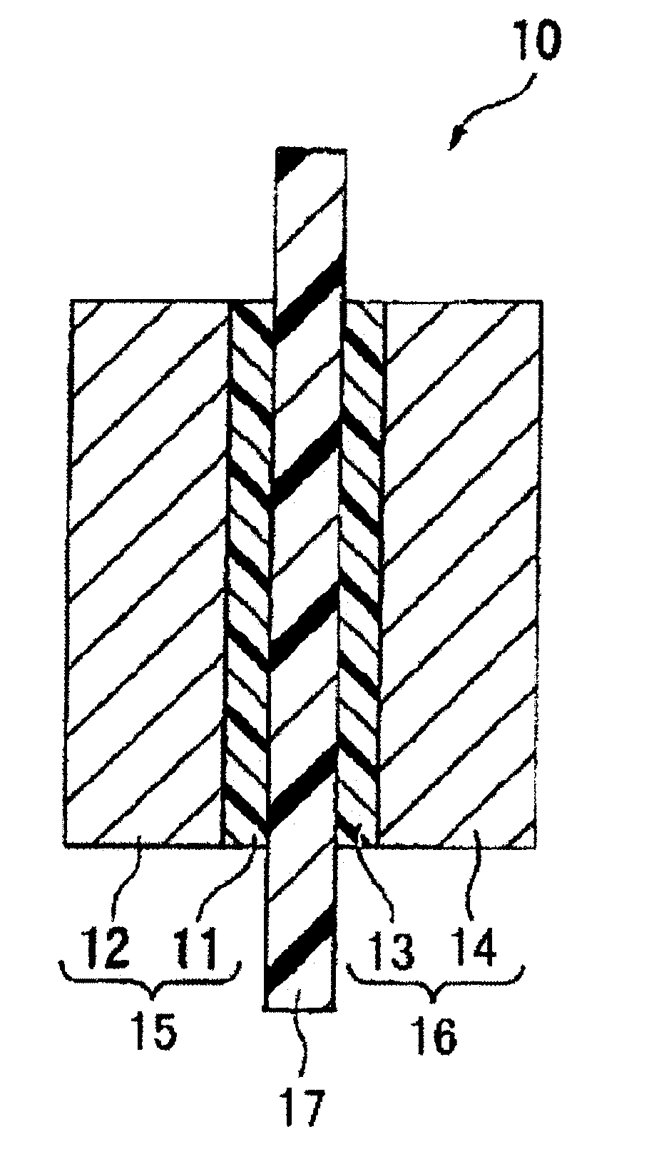
Membrane/electrode assembly for polymer electrolyte fuel cell and process for producing membrane/electrode assembly for polymer electrolyte fuel cell
a technology of electrolyte fuel cell and membrane, which is applied in the manufacture of cell components, final product manufacturing, electrochemical generators, etc., can solve the problems of fatal damage, difficult to effectively utilize exhaust heat for auxiliary machine power, and increase the electrical potential of the anode, so as to achieve high power generation performance, the effect of scarcely susceptible to deterioration in the performance of the electrod
- Summary
- Abstract
- Description
- Claims
- Application Information
AI Technical Summary
Benefits of technology
Problems solved by technology
Method used
Image
Examples
example 1
I. Process for Producing Membrane / Electrode Assembly (1)
Formation of Anode Catalyst Layer (1)
[0068]A powder of carbon carrier (d002 0.339 nm, specific surface area: 210 m2 / g) was dispersed in deionized water, followed by addition of a chloroplatinic acid aqueous solution and formaline, and the mixture was cooled to −10° C., followed by stirring. After the resultant was kept at −10° C. for 30 minutes, a 40% sodium hydroxide aqueous solution was slowly dropwise-added therein, and the mixture was refluxed and stirred for 1 hour, followed is by filtration.
[0069]Then, the washing operation was repeated by using deionized water until the pH of the filtrate became 7. after that, the resultant was dried at 80° C., followed by vacuum drying overnight to prepare an electrode catalyst having 20 mass % of platinum supported on carbon. Such an electrode catalyst was measured by the X-ray powder diffraction, and the particle size of the platinum was about 2.5 nm. 6.0 g of an anode catalyst having...
example 2
I. Process for Producing Membrane / Electrode Assembly (2)
[0079]A coating liquid (a)-2 was prepared in the same manner as in the process for producing the coating liquid (a)-1 of Example 1 except that the amount of iridium oxide hydrate (IrOx.(H2O)y, Ir metal content: 76.2%) having a specific surface area of 8.0 m2 / g by a BET measuring method, added, was changed to 0.30 g.
[0080]The coating liquid (a)-2 was applied on a polypropylene substrate film by a die coater, followed by drying for 10 minutes in a dryer at 80° C. to form an anode catalyst layer (2). The thickness of the anode catalyst layer (2), the iridium metal amount (M) (mg / cm2) in the iridium oxide hydrate and the ratio (C) / (M) of the carbon support (C) (mg / cm2) in the electrode catalyst and the iridium metal amount (M) (mg / cm2) in the iridium oxide hydrate are shown in Table 1.
[0081]A membrane / electrode assembly (2) was obtained in the same manner as in the process for producing the membrane / electrode assembly (1) of Exampl...
example 3
I. Process of Producing Membrane / Electrode Assembly (3)
[0083]A coating liquid (a)-3 was prepared in the same manner as in the process for producing the coating liquid (a)-1 of Example 1, except that the coating liquid was prepared by using fine particles of iridium oxide hydrate, having a specific surface area of 10 m2 / g by the BET method.
[0084]The coating liquid (a)-3 was applied on a polypropylene substrate film by a die coater, followed by drying for 10 minutes in a dryer at 80° C. to form an anode catalyst layer (3). The thickness of the anode catalyst layer (3), the iridium metal amount (M) (mg / cm2) in the iridium oxide hydrate and the ratio (C) / (M) of the carbon support (C) (mg / cm2) in the electrode catalyst and the iridium metal amount (M) (mg / cm2) in the iridium oxide hydrate are shown in Table 1.
[0085]A membrane / electrode assembly (3) was obtained in the same manner as in the process for producing the membrane / electrode assembly (1) of Example 1, except that the anode catal...
PUM
| Property | Measurement | Unit |
|---|---|---|
| specific surface area | aaaaa | aaaaa |
| thickness | aaaaa | aaaaa |
| specific surface area | aaaaa | aaaaa |
Abstract
Description
Claims
Application Information
 - R&D
- Intellectual Property
- Life Sciences
- Materials
- Tech Scout
- Unparalleled Data Quality
- Higher Quality Content
- 60% Fewer Hallucinations
Browse by: Latest US Patents, China's latest patents, Technical Efficacy Thesaurus, Application Domain, Technology Topic, Popular Technical Reports.
© 2025 PatSnap. All rights reserved.Legal|Privacy policy|Modern Slavery Act Transparency Statement|Sitemap|About US| Contact US: help@patsnap.com


