Hydraulic control device and pressure switch

a technology of hydraulic control device and pressure switch, which is applied in the direction of functional valve types, couplings, check valves, etc., can solve the problems of blockage of the discharge path to the reservoir, and achieve the effect of easy to tolera

Inactive Publication Date: 2013-10-08
HAWE HYDRAULIK SE
View PDF16 Cites 0 Cited by
  • Summary
  • Abstract
  • Description
  • Claims
  • Application Information

AI Technical Summary

Benefits of technology

[0004]It is an object of the invention to provide a hydraulic control device and a pressure switch of the kind as mentioned at the beginning, within which leakage losses are avoided when the pressure source operates while the discharge path to the reservoir is blocked, and which performs with minimised starting resistance for the drive motor of the pressure switch.

Problems solved by technology

This means that the discharge path to the reservoir becomes blocked after a delay but remains open during the start-up phase of the drive motor.

Method used


Image

  • Hydraulic control device and pressure switch
  • Hydraulic control device and pressure switch
  • Hydraulic control device and pressure switch

Examples


Embodiment Construction

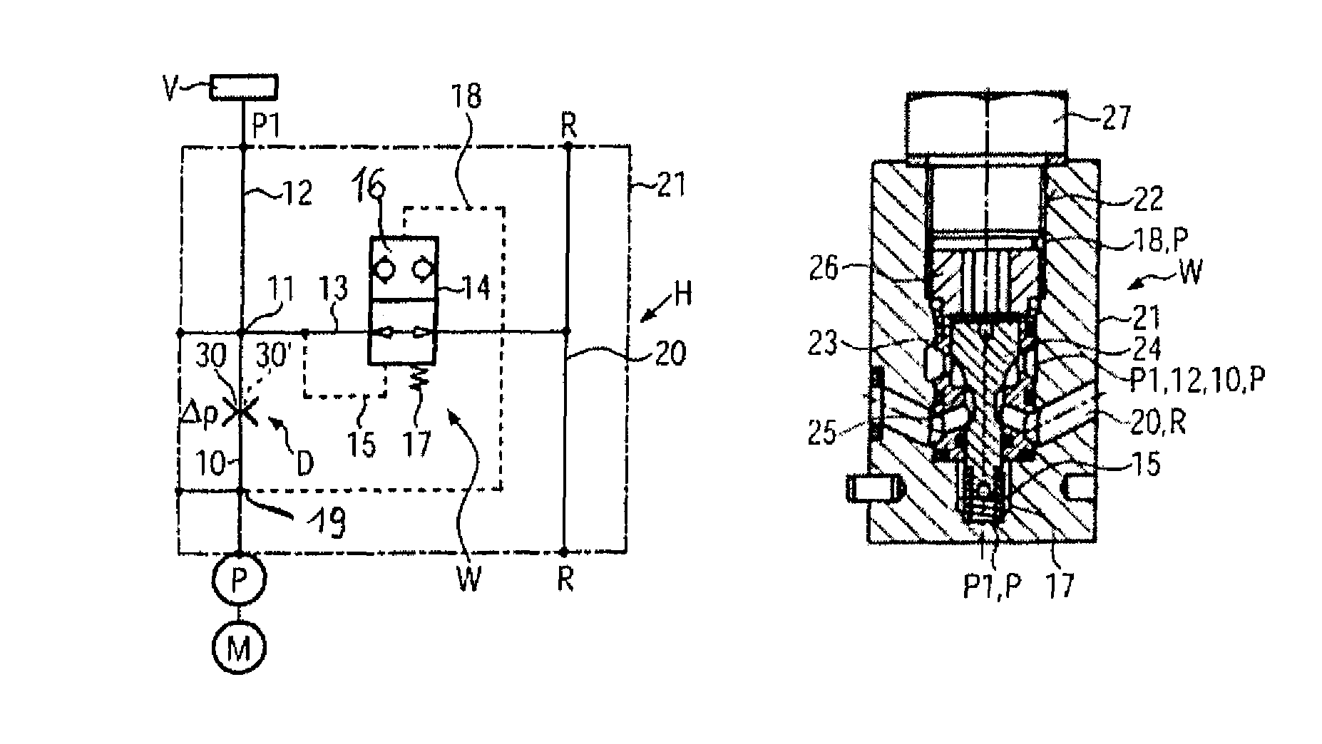
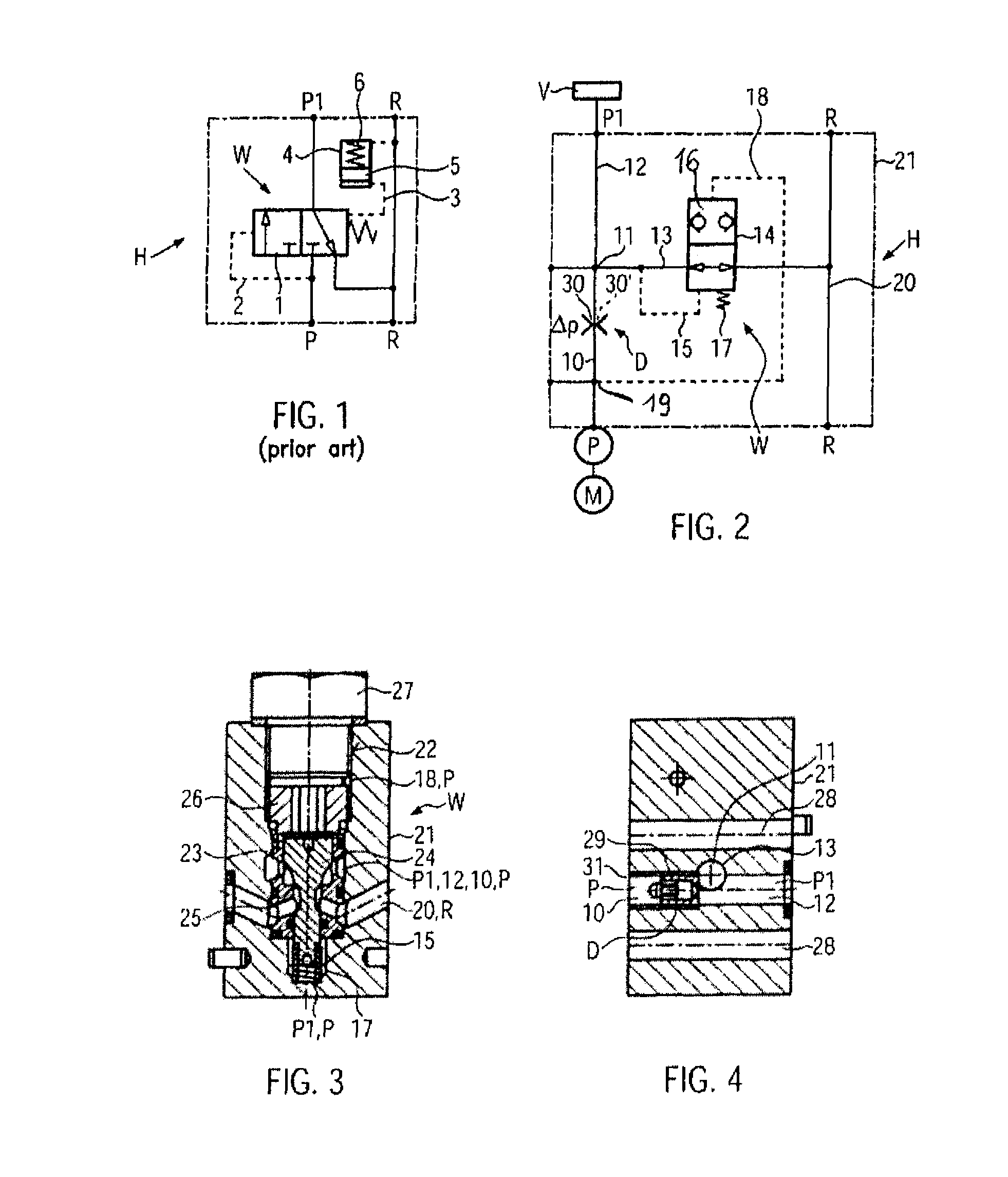
[0029]A hydraulic control device H (FIG. 1—prior art) comprises a 3 / 2 -multi-way slider valve 1 located between a pressure source P and a not shown valve assembly (pressure P1 acting at the valve assembly). The control member of the 3 / 2-multi-way slider valve 1 connects in pressure-free condition (first control position of the valve member, as shown) of the hydraulic control device H a line containing pressure P1 with a reservoir R, while a line to which the pressure source P is connected is blocked. This control position of the control member is assisted by a spring. The control member of the 3 / 2-multi-way slider valve 1 is actuated by a pilot pressure in a direction to a second control position. The pilot pressure originates from the pressure source P and acts in a pilot line 2. The control member is actuated parallel to the spring in the direction to the first control position by pilot pressure originating from the pressure P1 in a pilot line 3. The control member is formed as a ...


PUM


Abstract

In a hydraulic control device H comprising a pressure source P which can be switched on and switched off, a reservoir R and a pressure switch W located in a discharge path 13 from a valve assembly V to the reservoir R, which pressure switch W either connects the valve assembly V with the reservoir R or blocks the valve assembly V versus the reservoir R, the pressure switch W contains a displaceable control member 16 which is actuated in a first switching direction by a spring 17 and a pilot pressure originating from the pressure P1 acting at the valve assembly V and in a second switching direction to a control position blocking the discharge path 13 by a pilot pressure originating from the supply pressure of the pressure source, the pressure switch W is designed as a 2 / 2-multi-way seat valve 16 operating with a blocking position without leakage. A valve member 24 forms the control member 16 and co-operates with a valve seat 25 arranged in the discharge path 13. The pressure source P and the valve assembly V are permanently connected via a main channel 10, 11 containing a restrictor D. The discharge path 13 branches off from the main channel 10, 11, 12 between the valve assembly V and the restrictor D. The pilot pressure actuating the valve member 26 in the switching direction towards the valve seat 25 originates from the supply pressure taken between the pressure source P and the restrictor D.

Description

RELATED APPLICATIONS[0001]This application claims the benefit of and priority to European Patent Application No. 09005476.8, filed on 17 Apr. 2009, and European Patent Application No. 09007207.5, filed on 29 May 2009, all of which are incorporated by reference herein.BACKGROUND OF THE INVENTION[0002]The invention relates to a hydraulic control device according to the preamble of claim 1 and a to a pressure switch according to the preamble of claim 15.[0003]Hydraulic control devices containing a pressure switch are known in practice in various embodiments. In one embodiment (FIG. 1—prior art) the pressure switch is located within a main flow path between the pressure source and the valve assembly. The pressure switch is a 3 / 2-way slider valve and connects in one control position the pressure source with the valve assembly and separates the valve assembly from the reservoir. In the other control position the connection to the pressure source is blocked and the valve assembly is connec...

Claims


Application Information

Patent Timeline
Patent Type & Authority Patents(United States)
IPC IPC(8): F16D31/02
CPCF15B11/055F15B13/026F15B2211/40553F15B2211/41572F15B2211/45Y10T137/7904
Inventor NEUMAIR, GEORGKONIG, JOHANN
Owner HAWE HYDRAULIK SE
Why Eureka
Try Eureka