Visual-servoing optical microscopy
a technology of optical microscopy and visual servo, which is applied in the field of visual servo optical microscopy, can solve problems such as the application of lethal stresses on cells
- Summary
- Abstract
- Description
- Claims
- Application Information
AI Technical Summary
Benefits of technology
Problems solved by technology
Method used
Image
Examples
example i
Imaging Protocol for Repeatedly Returning to the Same Set of Cells
[0227]In these experiments, methods for repeatedly returning to the same set of cells in a culture are described. Using these methods, observations are made possible on one or more sets of living cells in a cell culture dish placed on a moveable microscope stage. Importantly, the dish can then be removed from the stage and placed in an incubator in order to allow the cells to grow, etc. The dish can then be placed on the microscope stage and the same set of cells automatically presented for observation. These steps can be repeated as many times as desired or needed.
[0228]In these experiments, responses of a set of cells (500-1000 cells at 10× magnification) can be monitored while various compounds are perfused into the culture dish. A stack of images consisting of a specified number of channels are acquired one or more times at specified intervals for a specified length of time. An editable (text) recipe file specifie...
example 2
Use of VSOM
[0248]In this Example, the equipment and other aspects of the VSOM of the present invention are described.
[0249]A. VSOM System Optical Platform
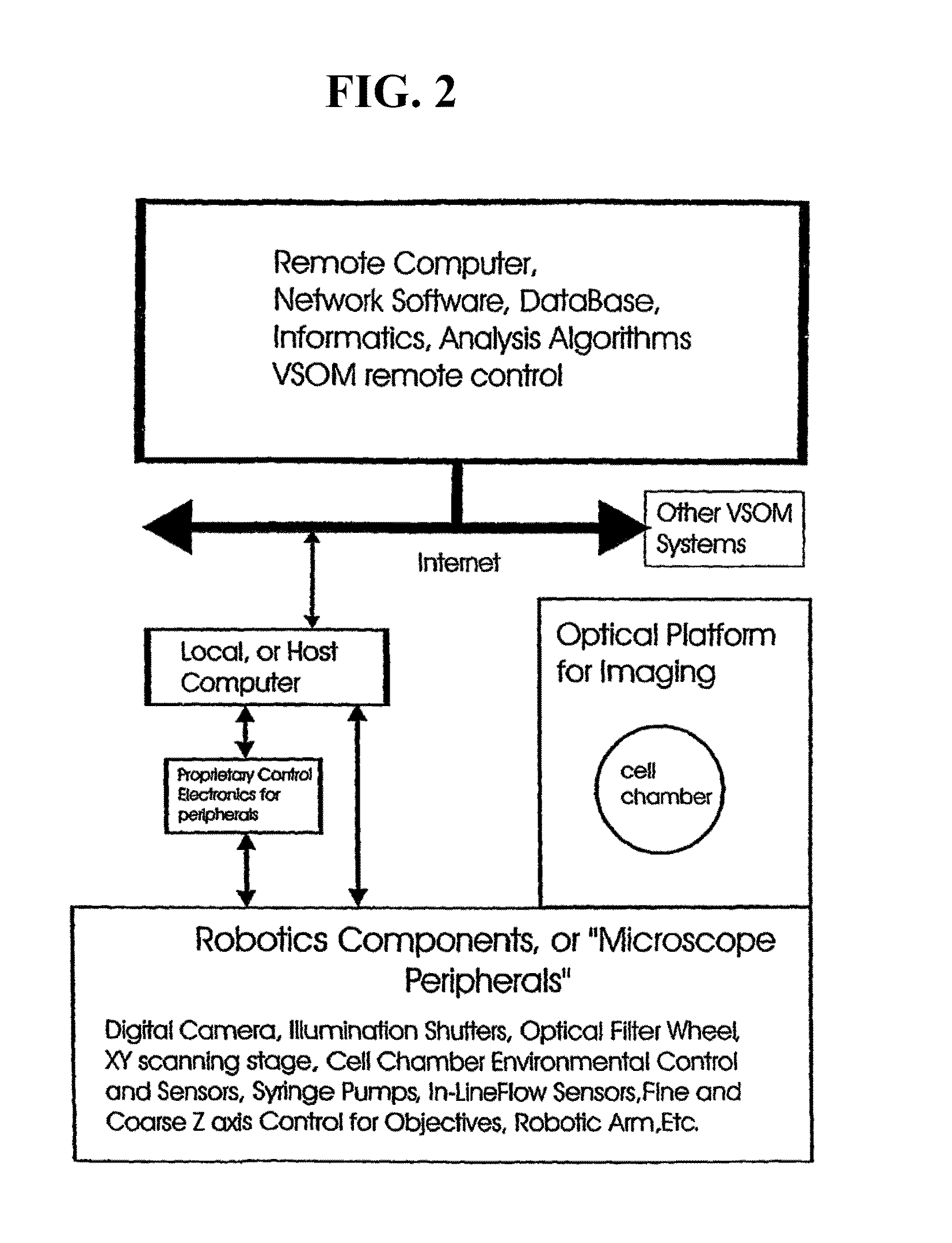
[0250]In most embodiments, a VSOM system is built around an inverted (i.e., the objective lens points upwards) fluorescence microscope because cell chambers and cell vessels are typically easier to design when the microscope has this geometry. However, cell chambers do exist that can be used with upright microscopes (where the objective lens points downwards). The VSOM of the present invention is suitable for use with such an optical platform. Biological research grade fluorescence microscopes are preferred, where the microscope has sufficient weight to be stable once the camera and microscope peripherals are mounted on the microscope. A standard 10× objective is sufficient for some VSOM experiments. Research grade microscopes, objectives and various peripherals are made by various manufacturers, including Carl Zeiss, Inc (Thornwoo...
example 3
VSOM Experiment
[0267]In this Example, a VSOM experiment conducted as described in Example 2 is described, with the indicated modifications.
[0268]The optical platform used was a Zeiss Axiovert 135 H / DIC, TV inverted microscope equipped for transmitted light (phase and DIC) and multi-color fluorescence microscopy. It was equipped with a computer-controlled xy scanning stage, z-axis stepping motor, and a six-position filter wheel (LUDL Electronic Products, Ltd. Hawthorne, N.Y.). A 12-bit Xillix CCD camera (Xillix Technologies, Vancouver, BC) containing a Kodak KAF-1400 CCD chip (1317×1035 pixels, 7×7 micron pixel size) was used for these studies. This camera has a readout rate of 8 MHz (i.e., approximately four full size images per set). Images from the camera were directly read out into the host computer, which was a Sparcstation Ultra 1, a multi-tasking UNIX workstation.
[0269]In addition, a Peltier temperature-controlled microperfusion chamber (PDMI-2 open chamber with TC-202 Biopola...
PUM
| Property | Measurement | Unit |
|---|---|---|
| concentrations | aaaaa | aaaaa |
| size | aaaaa | aaaaa |
| size | aaaaa | aaaaa |
Abstract
Description
Claims
Application Information
 - R&D
- Intellectual Property
- Life Sciences
- Materials
- Tech Scout
- Unparalleled Data Quality
- Higher Quality Content
- 60% Fewer Hallucinations
Browse by: Latest US Patents, China's latest patents, Technical Efficacy Thesaurus, Application Domain, Technology Topic, Popular Technical Reports.
© 2025 PatSnap. All rights reserved.Legal|Privacy policy|Modern Slavery Act Transparency Statement|Sitemap|About US| Contact US: help@patsnap.com


