Eureka AIR delivers breakthrough ideas for toughest innovation challenges, trusted by R&D personnel around the world.

Construction system and method for multi-floor buildings

a construction system and multi-floor technology, applied in the direction of shaping building parts, building components, cranes, etc., can solve the problems of major incidents, major cost charges for taller buildings, and traditional construction methods, and achieve the effect of avoiding public space occupancy

Active Publication Date: 2013-10-01
3L INNOGENIE
View PDF25 Cites 7 Cited by
  • Summary
  • Abstract
  • Description
  • Claims
  • Application Information

AI Technical Summary

Benefits of technology

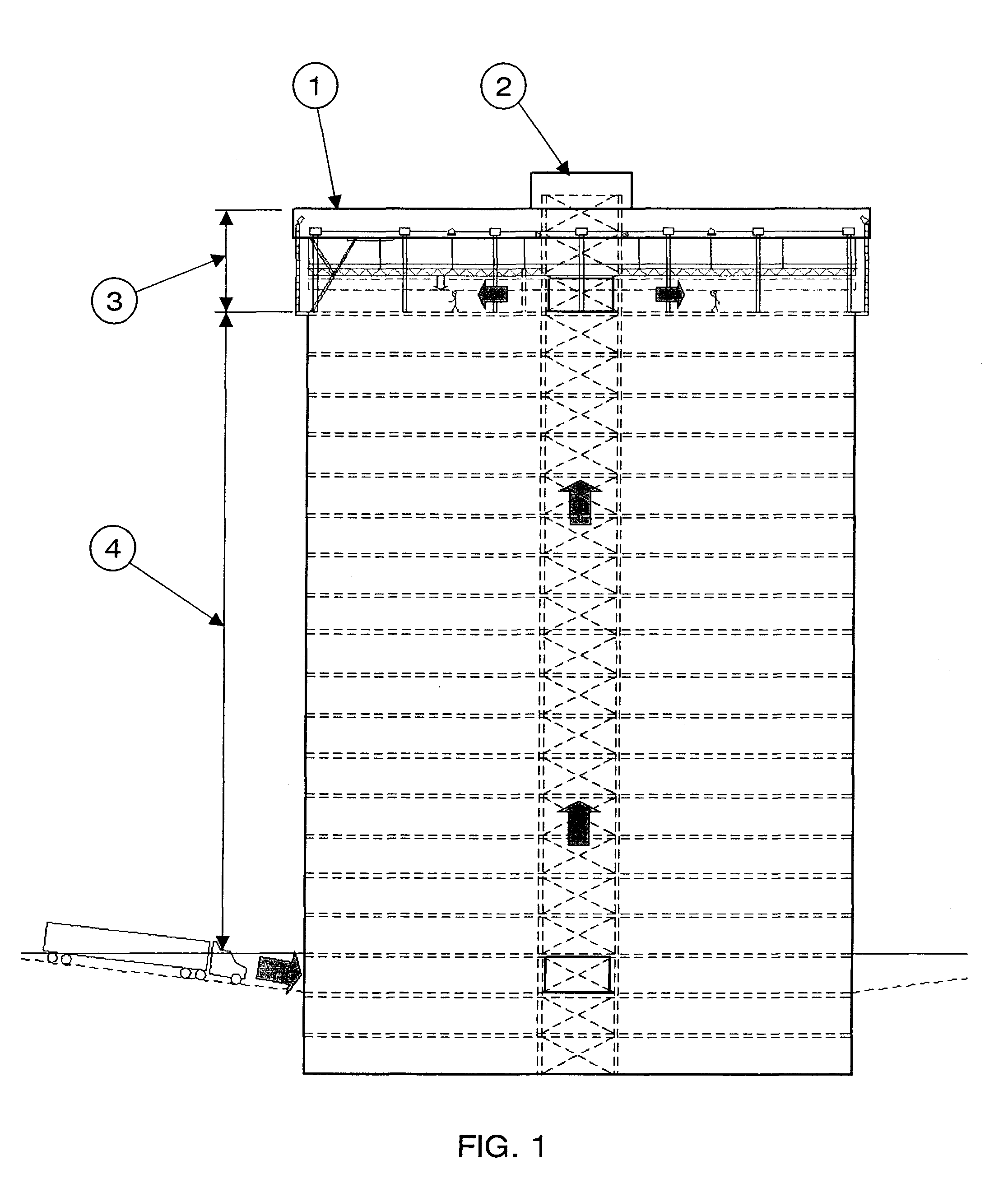
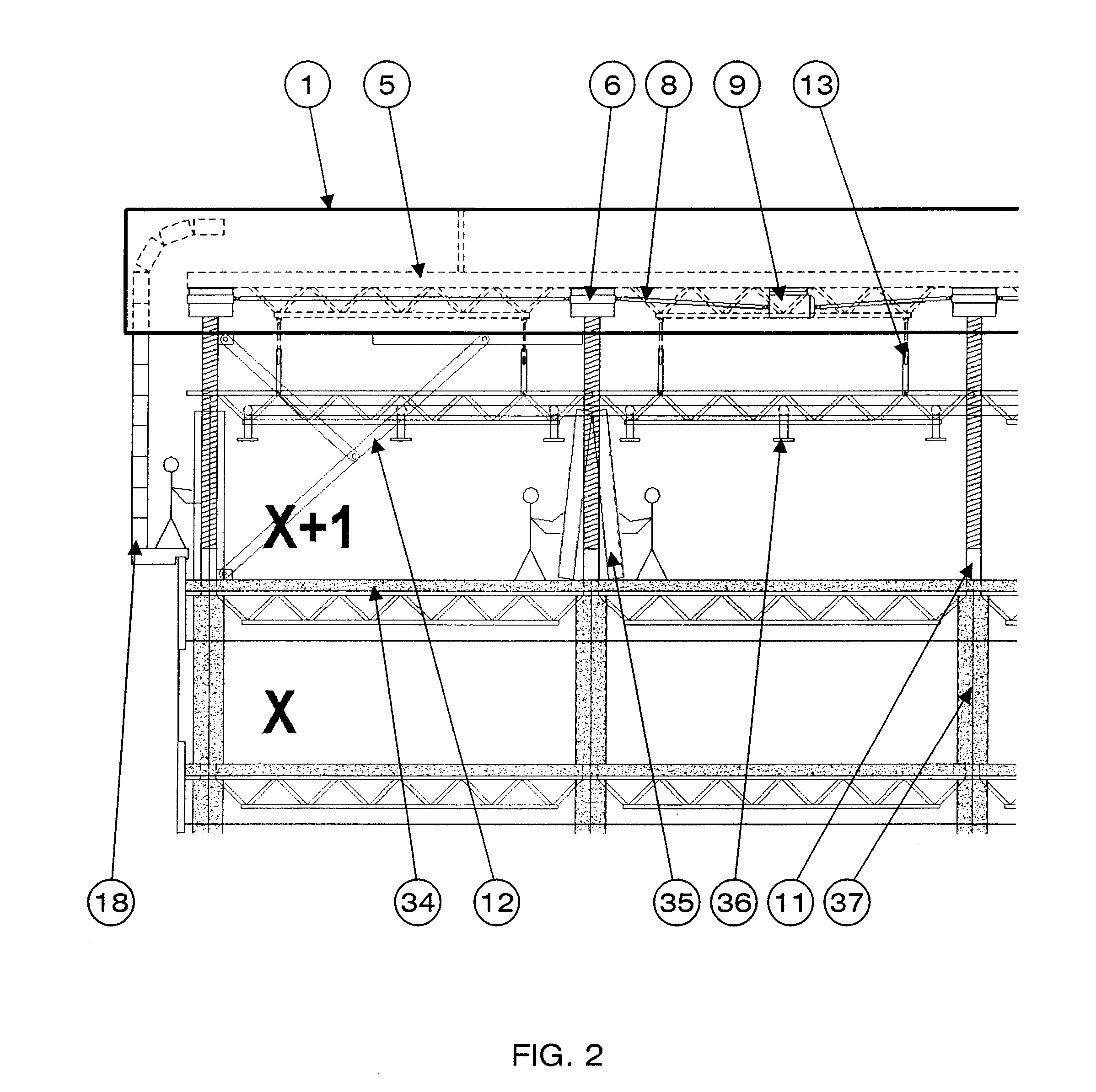
[0006]The system of the present invention includes a permanent roof structure equipped with multiple means for vertical displacement, such as extensible load support means, secured in said permanent roof structure. The multiple extensible load support means are synchronized and controlled to allow the permanent roof structure to be lifted in order to create a secure and protected construction zone, under the permanent roof structure, for at least one additional occupational floor to be built. The permanent roof structure can be lifted to create new construction zone as lower floors are completed and occupational need to do so arises. In order to provide the construction zone with the required materials, components, tools and workers, one or multiple means of vertical transportation and material handling, such as dedicated high capacity freight elevators are also part of the system. Such material handling means will allow construction to occur without affecting occupants of the building, its surroundings and its neighborhood and will avoid public space occupancy that typically occurs during conventional building construction. Vertical transportation of occupants is achieved with dedicated extensible elevators having the suspension and electric cables accumulated and available for future extension.
[0007]To secure the construction zone, the permanent roof structure is equipped with a wall enclosure system. The wall enclosure shields the construction zone on its entire perimeter, eliminating losses due to inclement weather conditions and protecting workers and neighborhood from the risks associated with the conventional method of construction. The disclosed construction system also incorporates adaptations to the elevators, and the mechanical and electrical systems of the building to allow their extensions when adding occupational floors without affecting services to the completed occupational floors below the construction area and to provide continuous services to the permanent roof structure and to workers in the construction zone.

Problems solved by technology

The traditional construction method poses real challenges when it comes to vertical transportation of the materials and workers.
Working high on open structures, using tower cranes and boom lifts handling materials up in the air represent a major source of incidents, injuries and even death of employees on a regular basis.
Tower cranes also represent significant cost charges for taller buildings.
Furthermore, the control of an open work environment is complex and difficult to maintain.
Other projects highly desirable on a long term time scale are impossible to realize with the conventional method because of the impact they would have in high density urban area or other specific area very sensible to the impacts of such projects.
The current construction methods are not flexible and very sensitive to changes and unpredictable situations that may arise during the project, sometimes affecting very badly the project profitability.
The owners and contractors have no flexibility on schedule and project scale when it comes to adapting to a sudden specific situation.
So far, construction projects methods only allowed occupancy after substantial completion of the construction, which delays significantly the revenues and affects the project financial balance.
Even with the best planning, large construction projects still represent important risks for those responsible for their completion.

Method used


Image

  • Construction system and method for multi-floor buildings
  • Construction system and method for multi-floor buildings
  • Construction system and method for multi-floor buildings

Examples


Embodiment Construction

Vertically Displaceable Permanent Roof Structure

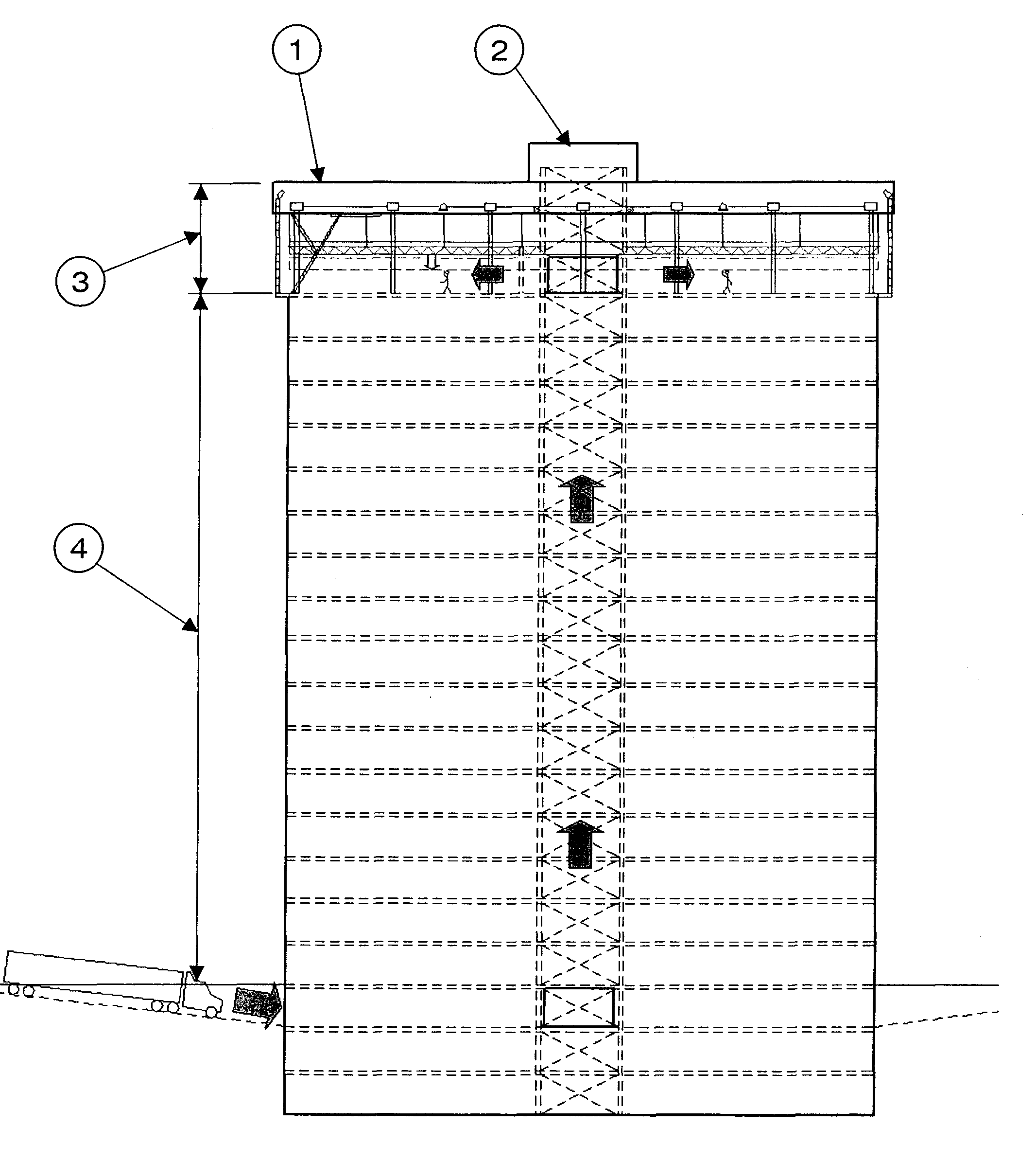
[0054]Referring now to the drawings, the present invention will be described. A permanent roof structure 1 is first assembled on a foundation 48 for the building construction. The shape of the foundation 48 needs to be similar to the shape desired for the floors to build in the future. The permanent roof structure 1 can have any shape, as long as it extends equal to or greater than the desired shape of the floor to build in the future.

[0055]The permanent roof structure 1 includes a structure 5 similar to those of conventional roof assemblies. The permanent roof structure 1 is moveable vertically using extensible load support means 6 that are motorized, synchronized and controlled. In order to add a floor when the occupational need to do so arises, the permanent roof structure 1 is raised to create a construction zone 3 under the permanent roof structure for at least one additional floor. Examples of extensible load support means 6 are ...


PUM


Abstract

A multi-floor building construction system for progressively constructing floors on load-bearing means of a foundation as the occupational need to do so arises and while sub-floors can be occupied. A permanent roof structure is displaceably supported over an uppermost floor of at least an upper one of one or more occupational floor spaces. Extensible load support means is secured in the roof structure until the completion of the mufti-floor building. The extensible load support means rests upon the uppermost floor to support the total load of the permanent roof structure. The extensible load support means is extendible downwardly to push against the uppermost floor to raise the permanent roof structure. Adjustable hoisting means is secured inside the permanent roof structure for lifting floor sub-assemblies fabricated in the construction zone using the extensible load support means while simultaneously raising the permanent roof structure.

Description

CROSS-REFERENCE TO RELATED APPLICATION[0001]The present application is a National Phase of International application No. PCT / CA2010 / 000161, filed Feb. 5, 2010, which claims priority on U.S. provisional patent application no. 61 / 150,813 filed on Feb. 9, 2009.TECHNICAL FIELD[0002]The present invention generally relates to the construction methods for multi-floor buildings and specifically to a multi-floor building construction system and method for progressively constructing floors on a foundation as the occupational need to do so arises while allowing previously constructed floors to be occupied.BACKGROUND ART[0003]Construction projects of multi-floor and tall buildings are becoming more and more important in terms of number of floors, number of employees involved in their construction, the financing requirements and the impact such projects have on the urban life of the project neighborhood.[0004]Many construction projects are completed in regions where weather conditions have a dir...

Claims


Application Information

Patent Timeline
Patent Type & Authority Patents(United States)
IPC IPC(8): E04G21/14E04B1/00
CPCE04B1/3527E04G13/02E04G21/28E04G21/242E04B7/16E04H1/06E04H3/00
Inventor LAROUCHE, JOEYLAROUCHE, GILLESLAROUCHE, JUSTIN
Owner 3L INNOGENIE
Why Eureka
Eureka Blog
Learn More