
Terminal device for cell voltage measurement of a fuel cell

a technology of cell voltage measurement and fuel cell, which is applied in the direction of fuel cells, electrochemical generators, instruments, etc., can solve the problems of difficult to use these in common for a plurality of types of fuel cells with mutually different cell thicknesses, and the inability to measure the cell voltage, so as to improve the workability of attaching to the fuel cell and the angle of the support member. , the effect of easy adjustmen

Active Publication Date: 2013-08-27
TOYOTA JIDOSHA KK
View PDF11 Cites 0 Cited by
  • Summary
  • Abstract
  • Description
  • Claims
  • Application Information

AI Technical Summary

Benefits of technology

The terminal device described in this patent makes it easier to attach a fuel cell to a terminal, improves the reliability of measuring cell voltage, and makes the contact plane of each cell small. This is achieved by allowing the angle of the support member to be adjusted when connecting terminals to the fuel cell, ensuring reliable contact even when rotating the terminals and using multiple types of fuel cells. The device also makes it easy to insert terminals between separators, making for simpler attachment to the fuel cell. These technical effects improve the workability and efficiency of the terminal device in fuel cell applications.

Problems solved by technology

Conventional terminal devices having a plurality of terminals have the intervals between terminals set in a fixed manner, so it is difficult to use these in common for a plurality of types of fuel cells with mutually different cell thicknesses.
Note that this kind of problem is not limited to polymer electrolyte fuel cells, but is a problem common to cell voltage measurement terminal devices for fuel cells containing a plurality of cells.
With this terminal device, the large diameter part functions as a retainer for each terminal, so it is possible to inhibit the terminals from being separated from the terminal contact parts of the fuel cell and making measurement of the cell voltage impossible.

Method used


Image

  • Terminal device for cell voltage measurement of a fuel cell
  • Terminal device for cell voltage measurement of a fuel cell
  • Terminal device for cell voltage measurement of a fuel cell

Examples


first embodiment

A. First Embodiment

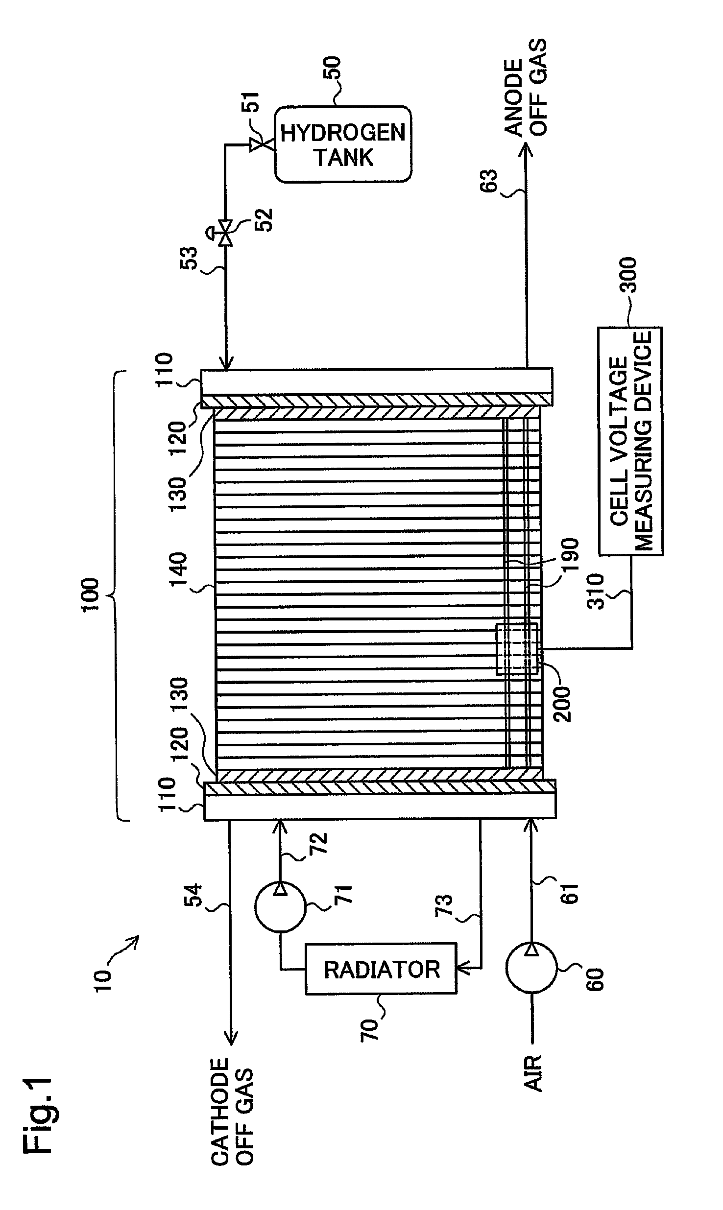
[0044]FIG. 1 is an explanatory drawing showing the schematic structure of a fuel cell system 10 of a first embodiment of the present invention. The fuel cell system 10 includes a fuel cell 100. The fuel cell 100 has a stacked constitution for which an end plate 110, an insulation plate 120, a collector plate 130, a plurality of cells 140, a collector plate 130, an insulation plate 120, and an end plate 110 are stacked in this order.

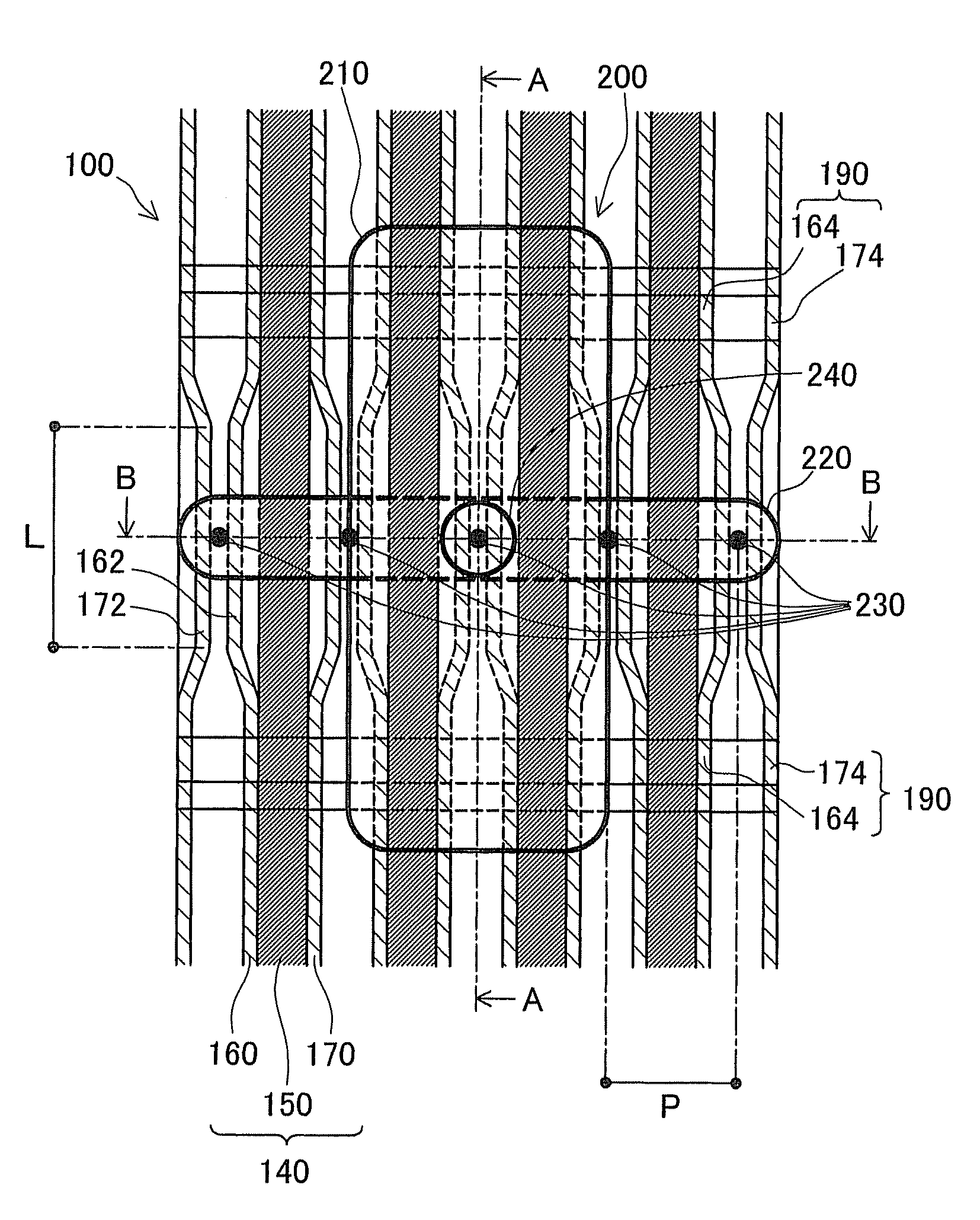
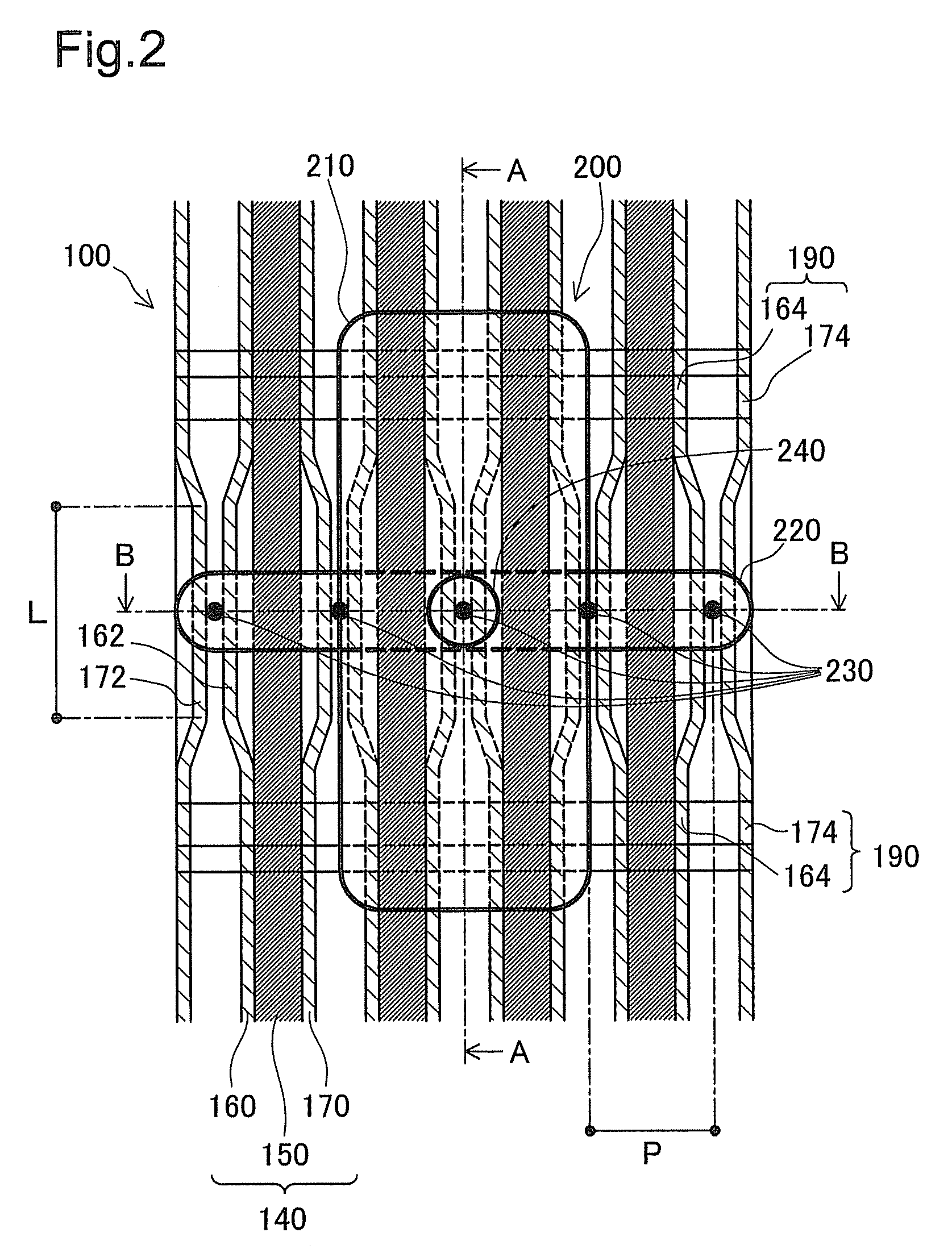
[0045]The fuel cell 100 of this embodiment is a polymer electrolyte fuel cell. Each cell 140 of the fuel cell 100 has a constitution for which a power generating module 150 including a membrane electrode assembly (also called “MEA”) for which an anode side catalyst layer and a cathode side catalyst layer are respectively arranged at both surfaces of an electrolyte membrane is held by a pair of separators (cathode side separator 160 and anode side separator 170) (see FIG. 2). The electrolyte membrane is an ion exchange membrane formed by...


PUM

PropertyMeasurementUnit
cell voltageaaaaaaaaaa
diameteraaaaaaaaaa
lengthaaaaaaaaaa

Abstract

A terminal device for cell voltage measurement of a fuel cell having a plurality of cells includes a plurality of terminals, a support member and a fixing member. The plurality of terminals each includes a conductive columnar part, and are electrically connected to the cells by the columnar part of each of the terminals being in contact with a conductive terminal contact part of a different cell of the fuel cell. The support member supports the terminals so that center axes of the columnar parts of the terminals are parallel to each other, and so that the center axes are aligned in one row at fixed intervals. The fixing member supports the support member so as to be able to rotate around a specified rotation shaft that is parallel to the center axes, and is attached to the fuel cell.

Description

[0001]This is a 371 national phase application of PCT / JP2010 / 002834 filed 20 Apr. 2010, the contents of which are incorporated herein by reference.TECHNICAL FIELD[0002]The present invention relates to a terminal device for cell voltage measurement of a fuel cell.BACKGROUND ART[0003]For example with a polymer electrolyte fuel cell, the voltage of each cell is measured (observed) to confirm that normal power generation is being performed with each cell, or to perform flow control of the reaction gases (fuel gas and oxidant gas). When measuring cell voltage, the terminals electrically connected to each cell of the fuel cell are used.[0004]A terminal device (terminal unit) having a plurality of terminals corresponding to a plurality of cells is known for measuring cell voltage for a plurality of cells of a fuel cell.SUMMARY[0005]With fuel cells, there are cases when the desired characteristics differ according to the application, for example. Because of that, there are cases when the sp...

Claims


Application Information

Patent Timeline
Patent Type & Authority Patents(United States)
IPC IPC(8): H01M8/04
CPCH01M8/04552H01M8/241Y02E60/50H01M2008/1095H01M8/2457G01R31/396G01R31/364G01R31/3835
Inventor HOTTA, YUTAKA
Owner TOYOTA JIDOSHA KK
Learn More