
Heat exchanger with radially arranged elements for isothermal chemical reactors

a technology of isothermal chemical reactors and heat exchangers, which is applied in the field of new heat exchangers, can solve the problems of large flanges, increased welding costs, and inability to substitute or extract heat exchanger parts for maintenance, and achieves the effect of less welding and low cos

Inactive Publication Date: 2013-06-11
CASALE SA
View PDF14 Cites 3 Cited by
  • Summary
  • Abstract
  • Description
  • Claims
  • Application Information

AI Technical Summary

Benefits of technology

The patent describes a new design for heat exchange elements that increases the surface area in contact with the fluid compared to conventional plate or tube units. The unique design allows for better movement of the fluid and reduces the risk of overheating, which can damage the catalyst and reduce the life of the catalyst. The design also allows for easy and economic realization and can replace conventional plates with a low-cost alternative. The tubes in the design act as channels for the fluid, providing more heat exchange surface compared to an equal size of a tube heat exchanger. Overall, the design improves heat exchange efficiency and lowers costs.

Problems solved by technology

Large flanges are more expensive and may pose problems of tightness; moreover, substitution or extraction for maintenance of a portion of a tube heat exchanger is generally not possible.
This is more challenging at the inlet of the fresh and highly reactive charge, where the thermal power of the reaction is greater, and in the outer region of the reaction zone (radial-inward flow), where the heat exchange elements are relatively distant from each other, due to their radial arrangement.

Method used


Image

  • Heat exchanger with radially arranged elements for isothermal chemical reactors
  • Heat exchanger with radially arranged elements for isothermal chemical reactors
  • Heat exchanger with radially arranged elements for isothermal chemical reactors

Examples


Embodiment Construction

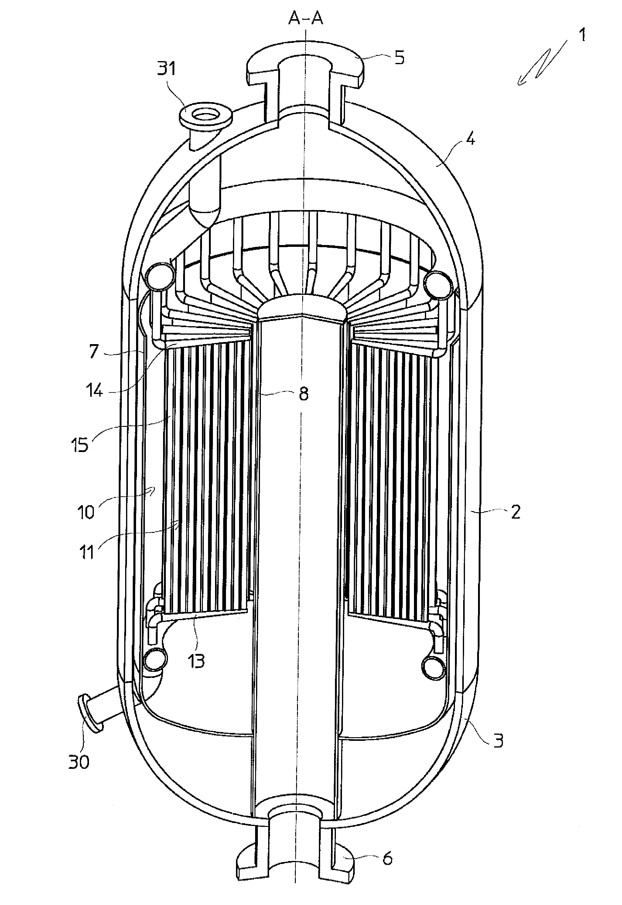
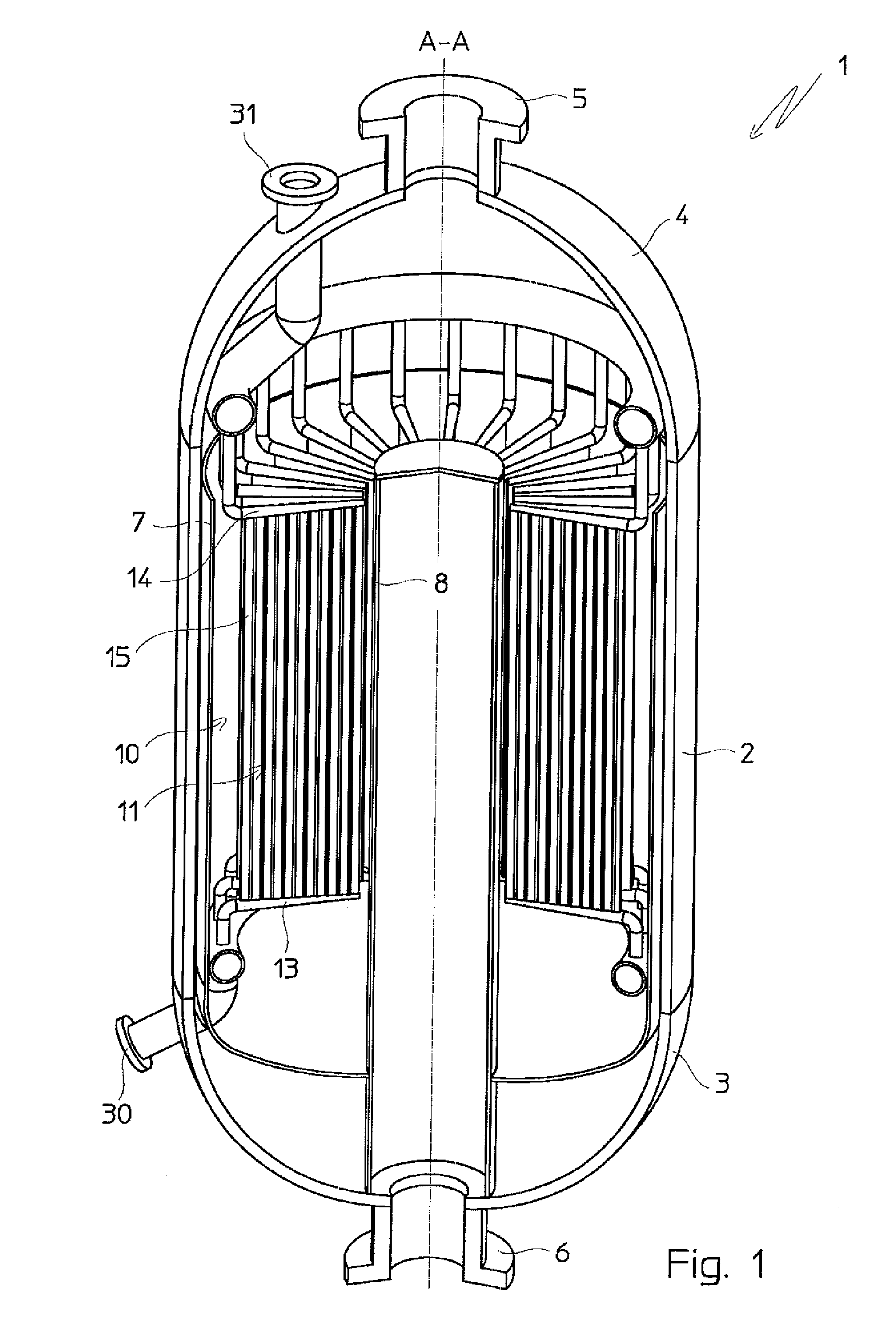
[0045]With reference to FIG. 1, an isothermal chemical reactor 1 comprises a cylindrical shell 2, with vertical axis A-A, a lower end 3 and an upper end 4, respectively equipped with an inlet flange 5 for the fresh charge of reagents and an outlet flange 6 for the products of the chemical reaction.

[0046]The example of FIG. 1 refers to a catalytic reactor, for example a methanol converter for the synthesis of methanol.

[0047]The reactor 1 contains an annular catalytic rack, which is per se known and not described in detail, containing an appropriate catalyst and externally delimited by a cylindrical perforated wall 7. The fresh charge of reagents enters from an interspace, between said wall 7 and the shell 2, flowing in a radial direction through the catalytic rack; the products of the reaction are collected in a central duct 8 in communication with the outlet flange 6.

[0048]The reaction takes place in the annular reaction space Q defined by the catalytic rack, between the wall 7 and ...


PUM


Abstract

An isothermal chemical reactor (1) comprising an array of radially arranged plate-like heat exchange elements (11) inside a reaction space, each element comprising feeding and collecting ducts and a bundle of parallel tubes (15) defining channels (12) for a heat exchange medium, the tubes (15) having an elongated cross section and being disposed with a variable orientation relative to the radial direction of the reactor, so that inner tubes near the axis of the reactor have the cross-section major axis aligned with said radial direction, and outer tubes have the same axis perpendicular to the radial direction. The preferred structure of a plate-like heat exchange element is also disclosed.

Description

FIELD OF THE INVENTION[0001]The invention relates to a novel heat exchanger suitable for use in isothermal or pseudo-isothermal chemical reactors. The invention relates, more in detail, to the heat exchanger, the heat exchange element thereof, and the reactor equipped with the heat exchanger.PRIOR ART[0002]Isothermal or pseudo-isothermal chemical reactors are reactors equipped with an internal heat exchanger to control the temperature of the reaction zone. In operation, the heat exchanger is fed with an appropriate cooling or heating medium, such as water, steam, etc. . . . and compensates for the heat generated or absorbed by the evolving chemical reaction, respectively exothermic or endothermic. Usually, the heat exchanger is immersed in a catalytic bed. Examples of such reactors are the methanol synthesis reactors and the shift converters, where a synthesis gas containing carbon monoxide is treated to convert the carbon monoxide into carbon dioxide.[0003]The known isothermal reac...

Claims


Application Information

Patent Timeline
Patent Type & Authority Patents(United States)
IPC IPC(8): B01J19/00F28F1/20F28F1/14B01J8/00F28D7/00F28F1/10F28F9/02F28F1/00F28F9/04
CPCB01J8/0214B01J8/0285B01J19/249F28F9/0263F28D7/0041F28D7/163F28D7/1684B01J2208/00132B01J2208/022B01J2219/2455B01J2219/2458B01J2219/2462B01J2219/2481B01J2219/2456
Inventor RIZZI, ENRICOFILIPPI, ERMANNOTAROZZO, MIRCOREDAELLI, LUCA
Owner CASALE SA
Learn More