Stiffness-enhanced surface-mounted piezoelectric devices
a piezoelectric device and stiffness technology, applied in piezoelectric/electrostrictive/magnetostrictive devices, piezoelectric/electrostriction/magnetostriction machines, electrical apparatus, etc., can solve the problems of increasing the probability of crystal or glass panel fracture, increasing the probability of warpage or deflection of the panel, and thus of the device. , to achieve the effect of enhancing the strength of the package and resisting deflection
- Summary
- Abstract
- Description
- Claims
- Application Information
AI Technical Summary
Benefits of technology
Problems solved by technology
Method used
Image

Examples
first embodiment
of Piezoelectric Device
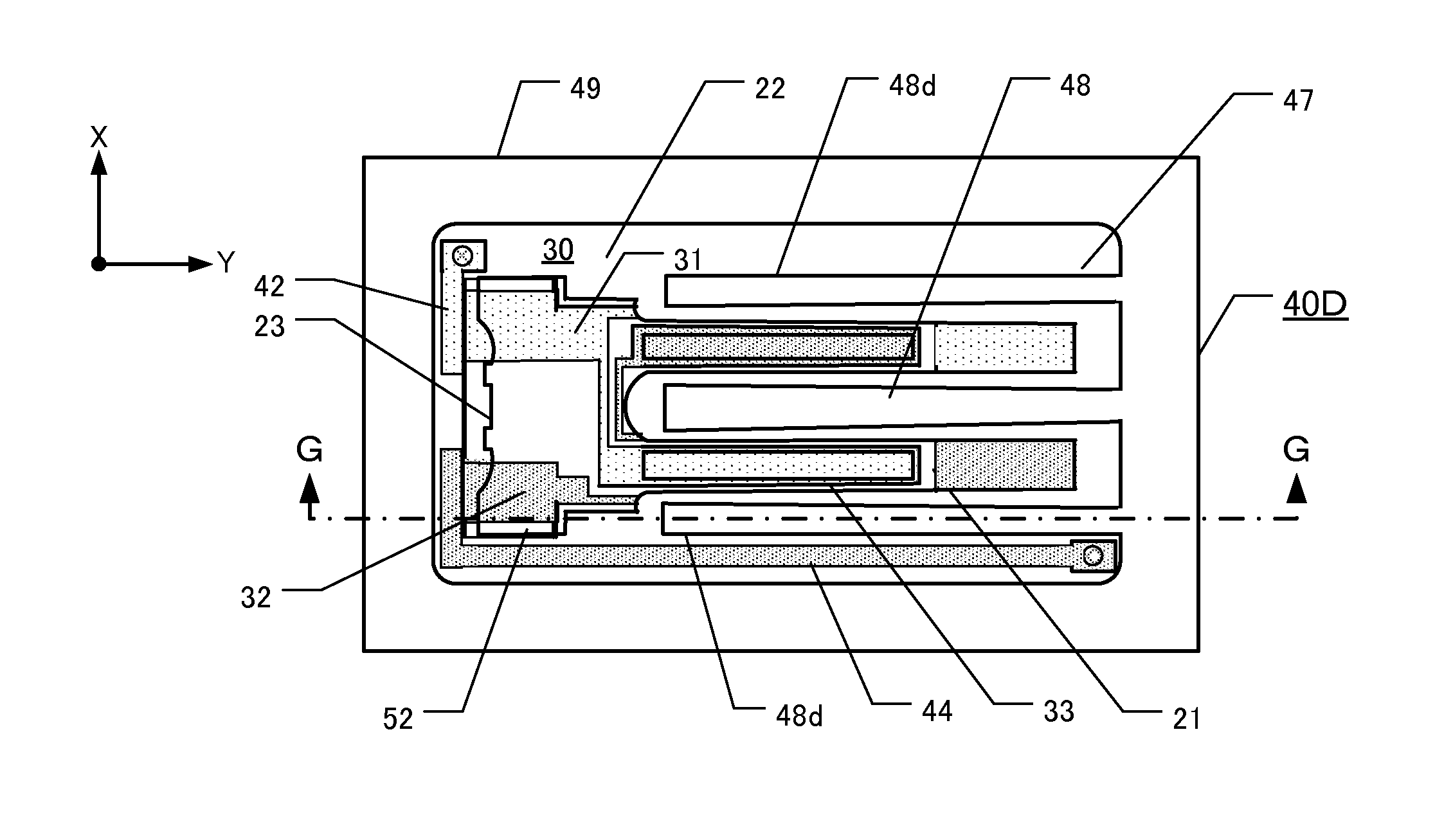
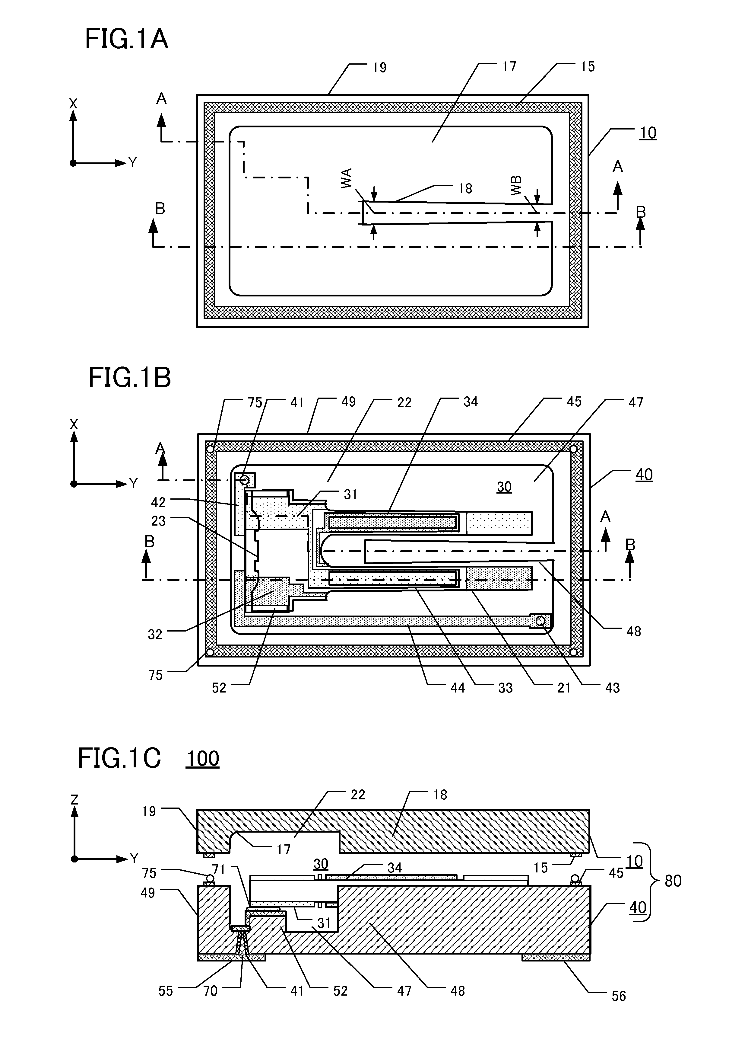
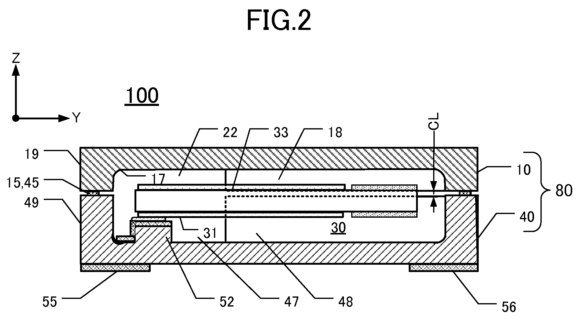
[0041]FIGS. 1A-1C are schematic depictions of this embodiment of a surface-mounted piezoelectric device 100 comprising a tuning-fork type crystal vibrating piece 30. FIG. 1A is a plan view of the inner surface of a package lid 10. FIG. 1B is a plan view of a package base 40 on which a tuning-fork type crystal vibrating piece 30 is mounted. FIG. 1C is an elevational section along the line A-A in FIGS. 1A and 1B, with the lid 10 and base 40 being shown vertically separated from each other. The piezoelectric device 100 comprises the lid 10 and base 40, which together form a package 80. The lid 10 and base 40 are made of glass or quartz crystal.
[0042]As shown in FIG. 1A, the inner surface of the lid 10 defines a lid concavity 17 and a lid columnar member 18, both facing the base 40 in the package. The lid concavity 17 and lid columnar member 18 are formed by etching or sand-blasting. The width WB (+Y-axis side, right side in FIG. 1A) of the lid columnar member 18 ...
second embodiment
of Piexoelectric Device
[0062]FIG. 4A is an elevational section of a second embodiment 110 of a piezoelectric device. FIG. 4B is a plan view of the device 110 after removing the lid 10A. The piezoelectric device 110 comprises a base 40A, having insulating properties, and a lid 10A. The lid 10A is made of KOVER® (an alloy of iron (Fe), nickel (Ni), and cobalt (Co)).
[0063]The base 40A comprises a bottom layer 51, a wall 49, a base columnar member 48a, and a pair of mounts 52. The base columnar member 48a extends into the center of the cavity 22, between the vibrating arms 21. The lid 10A does not include a columnar member. The wall 49 and base columnar member 48a are contiguous and have identical height. These features of the base 40A can be punch-pressed from ceramic “green sheets” each made from a slurry of ceramic powder (containing alumina and binder). The green sheets are stacked superposedly atop one another and fired to produce a laminated ceramic structure. Thus, the package 80...
third embodiment
of Piezoelectric Device
[0066]FIG. 5A is a plan view of the lid 10B of this embodiment 120, FIG. 5B is a plan view of the base 40B on which a tuning-fork type crystal vibrating piece 30 is mounted, and FIG. 5C is an elevational section along the line D-D in FIGS. 5A and 5B, but with the lid and base not yet bonded together.
[0067]This embodiment 120 includes a base columnar member 48b and a lid columnar member 18b. These columnar members are different from corresponding columnar members of the first embodiment 100. The third embodiment 120 comprises a lid 10B and a base 40B that are made of crystal. Differences from the first embodiment are described below.
[0068]One of the indicators of hardness of industrial materials is the “Knoop hardness.” A higher Knoop hardness number indicates increased hardness, and a lower Knoop hardness number indicates relative softness. The Knoop hardness number of borosilicate glass (commonly used for lids and bases) is 590 kg / mm2, and the Knoop hardness ...
PUM
 Abstract
Description
Claims
Application Information
 - R&D
- Intellectual Property
- Life Sciences
- Materials
- Tech Scout
- Unparalleled Data Quality
- Higher Quality Content
- 60% Fewer Hallucinations
Browse by: Latest US Patents, China's latest patents, Technical Efficacy Thesaurus, Application Domain, Technology Topic, Popular Technical Reports.
© 2025 PatSnap. All rights reserved.Legal|Privacy policy|Modern Slavery Act Transparency Statement|Sitemap|About US| Contact US: help@patsnap.com