Structure for a vehicle seat

a technology for vehicle seats and structures, applied in seat frames, chairs, transportation and packaging, etc., to achieve the effects of improving the cost-effectiveness of the vehicle seat, and improving the mechanical properties of the vehicle sea

Inactive Publication Date: 2013-05-07
ADIENT LUXEMBOURG HLDG SARL
View PDF37 Cites 8 Cited by
  • Summary
  • Abstract
  • Description
  • Claims
  • Application Information

AI Technical Summary

Benefits of technology

[0005]The object of the present invention is therefore the targeted formation or introduction of a filling in or into a cavity of a structural element of a vehicle seat in order to improve the mechanical properties of the vehicle seat, with a very cost-effective assembly process being sought in particular.
[0006]The object is achieved by means of a vehicle seat having a backrest and having a seat part, with the backrest or the seat part having at least one structural element which has a cavity, with the cavity being formed by a base plate and at least two profiles which are cohesively connected to the base plate, with a corner region of two profiles having provided in it a filling which is introduced to influence the stability and/or the deformation behavior of the backrest and/or of the seat part, with the filling having a foam support and a foam material, with the foam material at least partially surrounding the foam support, and the foam material preferably completely surrounding the foam support. In this way, an improvement in the mechanical properties of the vehicle seat can be obtained in a simple manner in that the filling is arranged and formed such that, during the formation of the

Problems solved by technology

It is disadvantageous in the known vehicle seats that, in part, the cavity is always completely fill

Method used


Image

  • Structure for a vehicle seat
  • Structure for a vehicle seat
  • Structure for a vehicle seat

Examples


Embodiment Construction

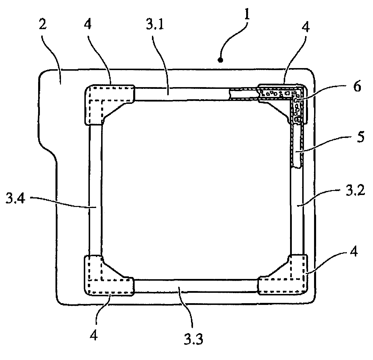
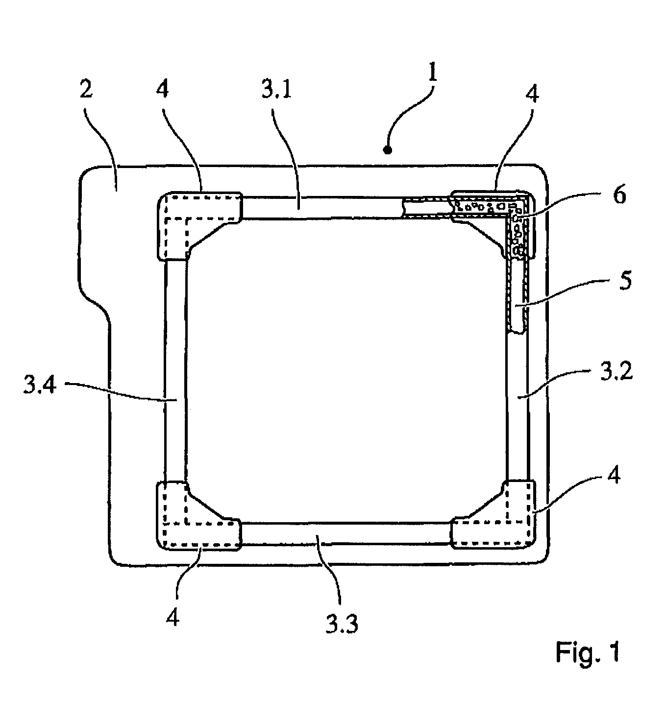
[0014]By way of example, FIG. 1 schematically illustrates, as an example of a structural element of a vehicle seat, the rear view of a seat back segment 1 of a backrest. The seat back segment 1 or the seat back structure 1 (the figure shows only a seat back segment 1 of, for example, a split foldable backrest) comprises a base plate 2 and four U-shaped profiles 3.1 to 3.4 which are placed thereon and which, together with the base plate 2 and preferably the corner pressed parts 4 placed thereon, a rectangular frame with an encircling hollow chamber 5. The base plate 2 and the profiles 3.1 to 3.4 are composed substantially of for example metal, in particular steel or aluminum sheet, or substantially of plastic, for example glass-fiber-reinforced plastic. The profiles 3.1 to 3.4 are connected to the base plate 2 for example by welding or adhesive bonding. The connection and / or stiffening of the profiles 3.1 to 3.4 with one another or with the corner pressed parts 4 takes place accordin...


PUM


Abstract

A vehicle seat includes a backrest and a seat part, at least one of which has a structural element with a cavity. The cavity is formed by a base plate and at least two profiles secured to the base plate. A corner region of the two profiles has provided in it a filling configured to influence the stability and/or the deformation behavior of the backrest and/or the seat part. The filling has a foam support and a foam material at least partially surrounding the foam support.

Description

CROSS REFERENCE TO RELATED APPLICATIONS[0001]This application claims priority from and the benefit of PCT Application No. PCT / EP2008 / 005729, filed on Jul. 14, 2008; German Patent No. DE 10 2007 033 774.6, filed on Jul. 18, 2007; and German Patent DE 10 2007 053 961.6, filed on Nov. 9, 2007; all entitled “Structure for a Vehicle Seat”, which are herein incorporated by reference.BACKGROUND[0002]The invention relates to a structure for a vehicle seat, which structure comprises rigid structure components which form cavities and comprises a foam structure which at least partially fills the cavities.[0003]Such vehicle seats are generally known. For example, the German laid-open specification DE 102 14 476 A1 and the German laid-open specification DE 103 21 289 A1 respectively disclose a frame composed of hollow profiles and a backrest of a vehicle seat, with a foam being arranged in each case in cavities of structural elements. Furthermore, the German laid-open specification DE 10 2004 04...

Claims


Application Information

Patent Timeline
IPC IPC(8): A47C7/02B29C44/04B68G7/00B60N2/90
CPCB29C44/18B60N2/68B60N2/42709Y10T29/481
Inventor ZYNDA, MARTINJOSTEN, STEFANFUNK, STEFANENGELS, BERNDHANSEN, ANDREAS
Owner ADIENT LUXEMBOURG HLDG SARL
Why Eureka
Try Eureka