
Apparatus, system, and method for improving the rate of deceleration of an engine

a technology of automatic transmission and engine, applied in the direction of electrical control, combustion engines, vehicles using one gear ratio, etc., can solve the problems of automatic transmissions not being able to transfer the large amount of torque produced by engines, requiring skill and tiresomeness, etc., to improve the rate of deceleration of engines, increase backpressure, and improve the effect of engine deceleration ra

Active Publication Date: 2013-04-30
CUMMINS INC
View PDF15 Cites 0 Cited by
  • Summary
  • Abstract
  • Description
  • Claims
  • Application Information

AI Technical Summary

Benefits of technology

The solution enables more precise and controlled engine deceleration, reducing the likelihood of rough shifts and driveline stress, while minimizing the use of engine brakes, resulting in smoother gear transitions and reduced wear on engine and transmission components.

Problems solved by technology

Without a transmission, a vehicle would be limited to using one gear ratio.
However, heavy duty trucks often require 10 or more gears, and shifting through each of those gears to get the heavy duty truck up to speed requires skill and can be tiresome.
However, automatic transmissions are not able to transfer the large amounts of torque produced by the engines of heavy duty trucks.
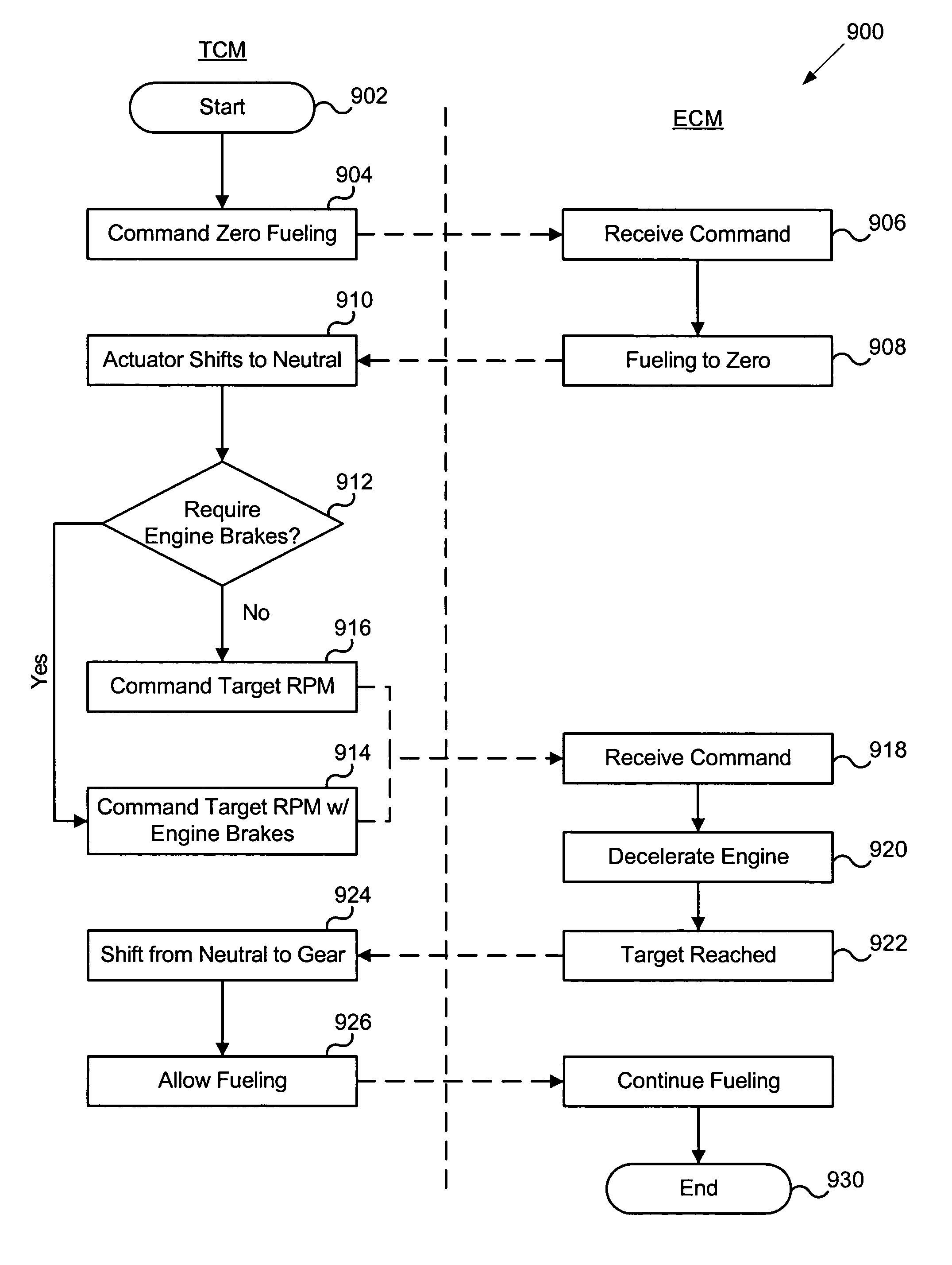
For example, while the initial target engine speed may have been 1400 revolutions per minute (RPM) when the transmission first started the shift event, the time spent at zero engine torque causes the vehicle to slow and thereby cause the target synchronization speed to drop.
In other words, by the time the engine reaches the target speed and allows the transmission to go into gear, the engine speed is too low to accelerate the truck in that gear.
Such an event causes a rough shift event, noticeable drive shaft ringing or vibrations, and causes undue wear on the engine and transmission.
However, the use of engine brakes brings about new performance challenges.
Therefore, even when engine brakes are requested, the engine initially decelerates at the natural rate, and subsequently extremely fast once the engine brakes have activated.
The combination of this extreme deceleration rate and engine brake hydromechanical deactivation delays make it difficult for the engine governor to catch the engine at the target synchronization speed and often cause the engine to “overshoot” the target synchronization speed.
This results in rough shift events and undesired driveline component abuse.

Method used


Image

  • Apparatus, system, and method for improving the rate of deceleration of an engine
  • Apparatus, system, and method for improving the rate of deceleration of an engine
  • Apparatus, system, and method for improving the rate of deceleration of an engine

Examples


Embodiment Construction

[0032]Many of the functional units described in this specification have been labeled as modules, in order to more particularly emphasize their implementation independence. For example, a module may be implemented as a hardware circuit comprising custom VLSI circuits or gate arrays, off-the-shelf semiconductors such as logic chips, transistors, or other discrete components. A module may also be implemented in programmable hardware devices such as field programmable gate arrays, programmable array logic, programmable logic devices or the like.

[0033]Modules may also be implemented in software for execution by various types of processors. An identified module of executable code may, for instance, comprise one or more physical or logical blocks of computer instructions which may, for instance, be organized as an object, procedure, or function. Nevertheless, the executables of an identified module need not be physically located together, but may comprise disparate instructions stored in d...


PUM


Abstract

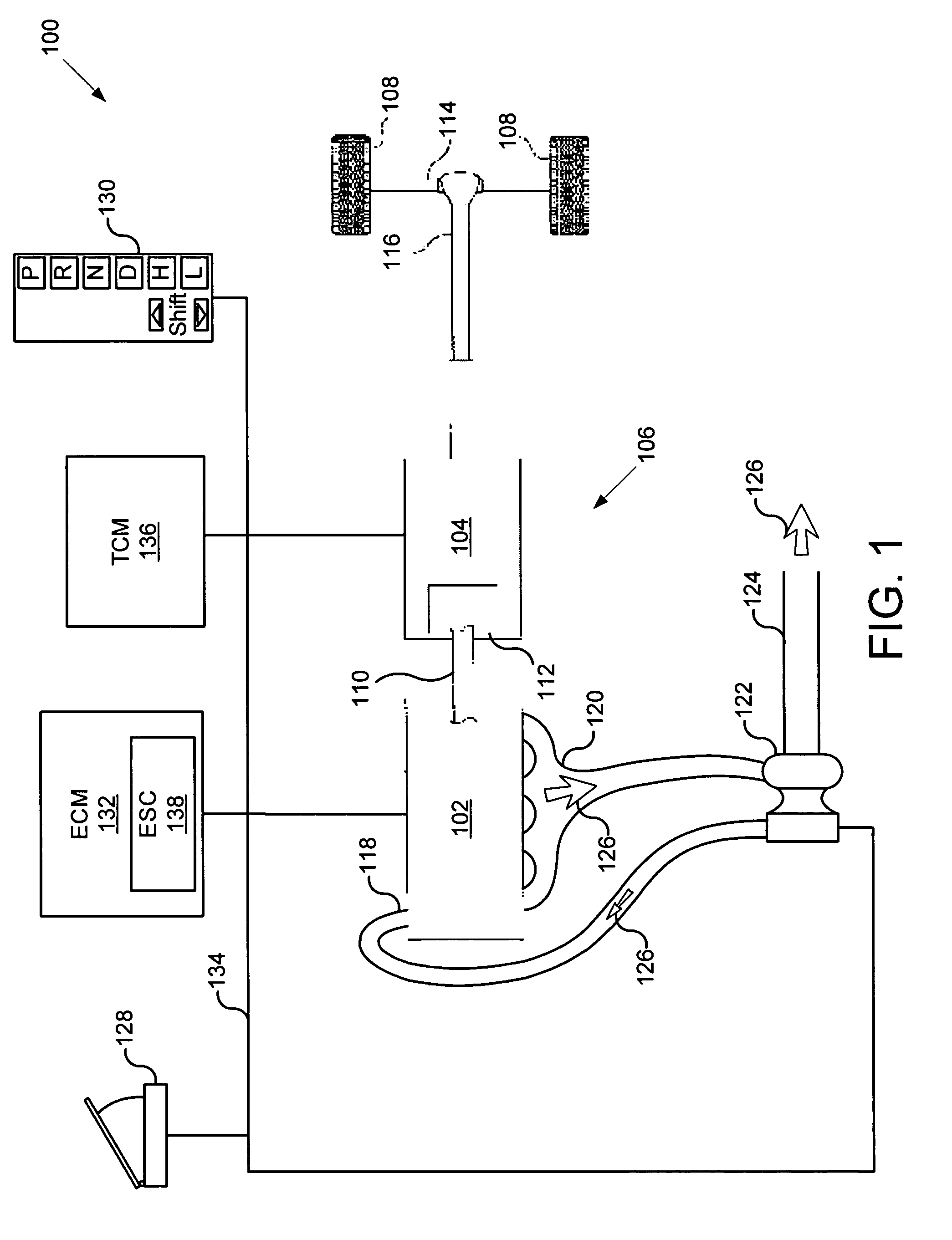
An apparatus, system, and method are disclosed for improving the rate of deceleration of an engine. The apparatus may include an engine control module configured to communicate with a transmission control module, and an engine speed control module configured to increase the rate of deceleration of an engine. The system includes the apparatus and a vehicle having a turbocharged internal combustion engine coupled to an automated manual transmission. The method includes requesting a target engine speed during a shift event, monitoring engine operating parameters, and increasing the rate of deceleration of an engine.

Description

BACKGROUND OF THE INVENTION[0001]1. Field of the Invention[0002]This invention relates to shift events of automotive transmissions and more particularly relates to improving the rate of deceleration of an engine to improve shift quality of automated manual transmissions.[0003]2. Description of the Related Art[0004]The purpose of an automotive transmission is to allow an engine to operate within a narrow range of speeds while outputting a broad range of speeds. Without a transmission, a vehicle would be limited to using one gear ratio. Vehicles need transmissions to take advantage of the narrow rpm ranges of the engine where horsepower and torque are at a maximum. The transmission allows the gear ratio between the engine and the drive wheels to change as the vehicle speeds up and slows down. Shifting gears allows the engine to stay near the rpm range that will provide the best performance.[0005]At least three different types of transmissions have been developed over the past century ...

Claims


Application Information

Patent Timeline
Patent Type & Authority Patents(United States)
IPC IPC(8): F16H47/08F16H47/10
CPCF02B37/24F02D31/001F02D41/023F02D41/0007Y10T477/677Y02T10/144Y02T10/42Y10T477/55Y02T10/12Y02T10/40
Inventor KING, BRIAN J.MOORE, GREG A.SINKHORN, AMY S.
Owner CUMMINS INC
Learn More