
Vehicle control apparatus

a technology for controlling apparatus and vehicles, applied in the direction of ignition automatic control, dynamo-electric converter control, instruments, etc., to achieve the effects of reducing accessory load, increasing the amount of electricity generation, and reducing temperatur

Active Publication Date: 2013-04-16
TOYOTA JIDOSHA KK
View PDF17 Cites 5 Cited by
  • Summary
  • Abstract
  • Description
  • Claims
  • Application Information

AI Technical Summary

Benefits of technology

The invention is a vehicle control system that can better manage the output of the engine and another control, such as the load torque of an alternator. The system includes an accessory that generates electricity from the engine's torque, and adjusts the engine's output by changing the load it generates. The system also has an electricity storage device that stores the electricity generated by the accessory and an ignition timing control that adjusts the engine's timing to optimize torque output. Additionally, the system includes a speed ratio shift apparatus that changes the engine's torque output at different speeds, and a speed ratio shift control that adjusts the timing of the shift to optimize engine power output. The system can also adjust the accessory load to optimize its output of electricity, depending on the engine's torque output and the speed of the accessory. Overall, the system allows for more effective control of the engine and other accessories, resulting in improved performance and efficiency.

Problems solved by technology

However, since even air is subject to inertia, the intake air amount tends not to immediately change when the degree of opening of the throttle valve is adjusted but to change after a delay following the adjustment of the degree of opening of the throttle valve.

Method used


Image

  • Vehicle control apparatus
  • Vehicle control apparatus
  • Vehicle control apparatus

Examples


first embodiment

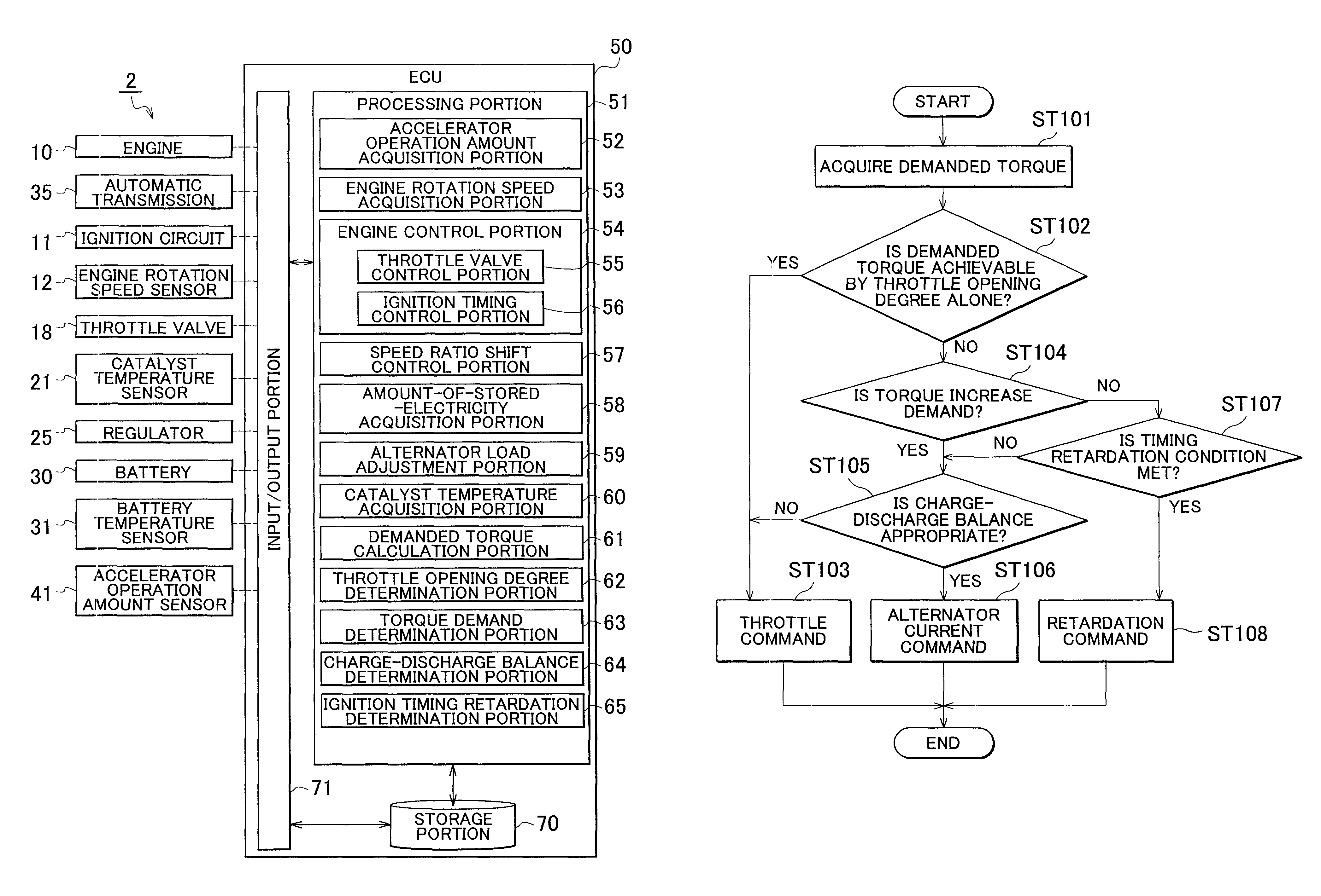
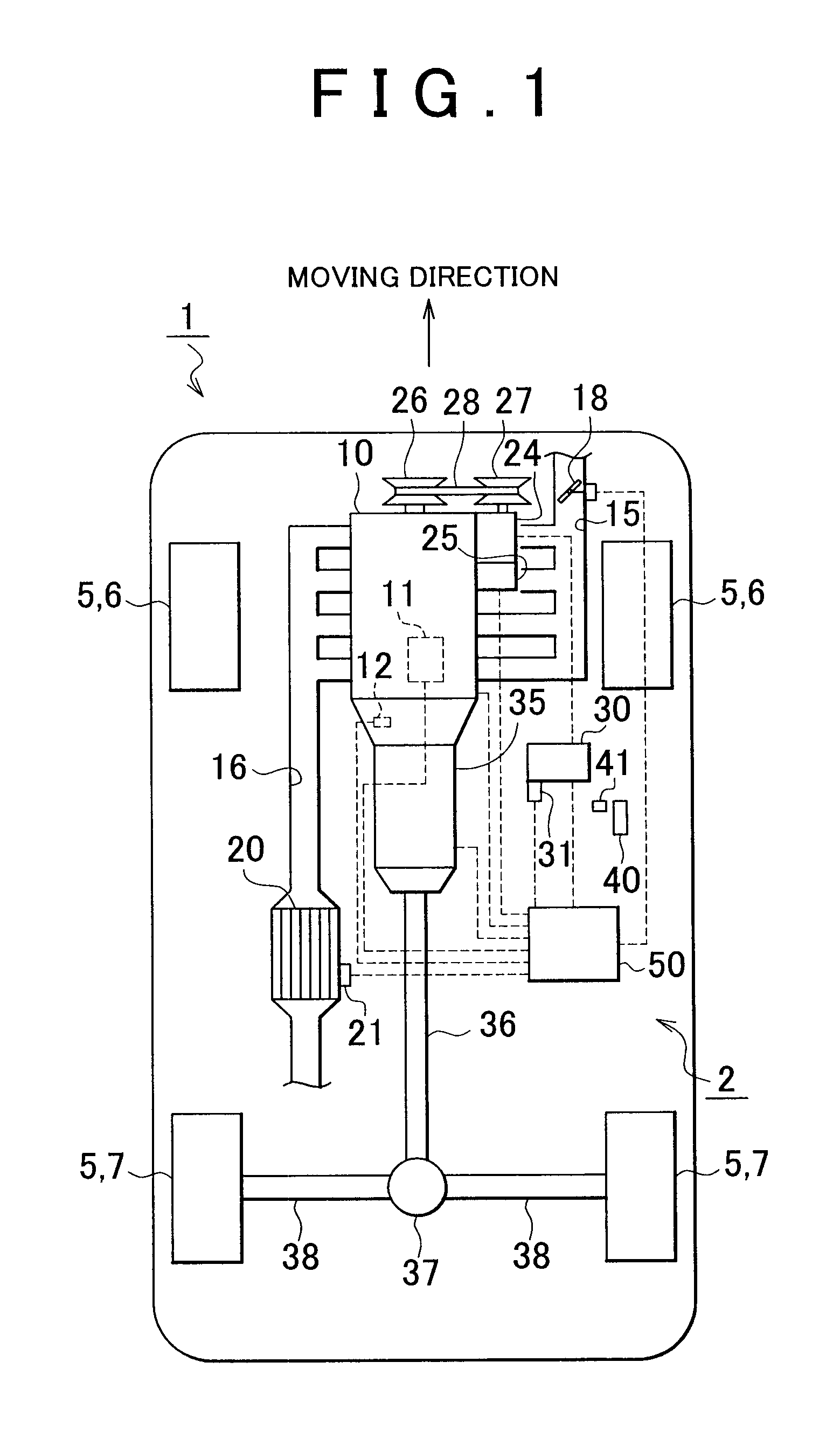
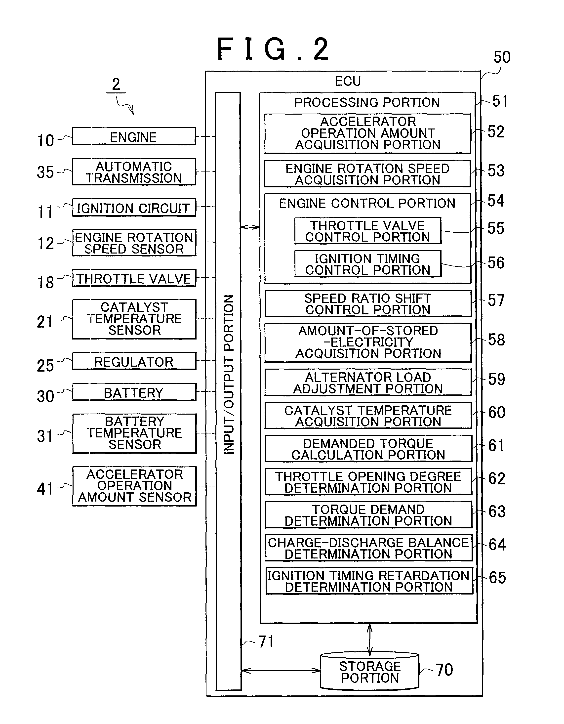
[0051]The vehicle control apparatus 2 in accordance with the first embodiment is constructed as described above, and operation of the vehicle control apparatus 2 will be described below. At the time of travel of the vehicle 1, the vehicle control apparatus 2 detects the accelerator operation amount that is the amount of operation of the accelerator pedal 40 that is operated by a driver, via the accelerator operation amount sensor 41 that is provided in the vicinity of the accelerator pedal 40, and acquires results of this detection via the accelerator operation amount acquisition portion 52 provided in the processing portion 51 of the ECU 50. The accelerator operation amount acquired by the accelerator operation amount acquisition portion 52 is transferred to the engine control portion 54 that is provided in the processing portion 51 of the ECU 50. On the basis of the transferred accelerator operation amount, various portions of the engine 10 are controlled by the engine control por...

second embodiment

[0136]Besides, the vehicle control apparatus 80 in accordance with the second embodiment is able to perform the traction control and the vibration restraint control. In the traction control and the vibration restraint control, torque is increased or decreased within short time. Therefore, in the case where the control of torque is performed by the coordinated control combining the control of the degree of throttle opening and the control of the alternator load while the traction control or the like is being performed, the reduced amount of time needed for increasing or decreasing the alternator load contributes to the ability to control the torque without having a great adverse influence on the charge-discharge balance.

[0137]Incidentally, the torque decrease during the traction control is high in the degree of urgency. Therefore, in the case where the amount of control of the torque decrease achieved by employing only the control of the alternator load is not sufficient, the retarda...

third embodiment

[0179]FIG. 12 is an illustrative diagram of the gains of the retardation control of the ignition timing and the control of the alternator load relative to the battery temperature. Various controls performed when the vehicle control apparatus 90 in accordance with the third embodiment controls the torque in conjunction with the demanded torque while the vehicle is travelling. For example, in the case where a coordinated control combining the retardation control of the ignition timing and the control of the alternator load is performed on the basis of the state of the battery 30, the temperature of the battery 30 is also taken into consideration. That is, since the battery 30 declines in the charging efficiency in the case where temperature is low, the amount of electricity generated by the alternator 24 is increased if the battery temperature that is the temperature of the battery 30 declines.

[0180]Concretely, when the torque control through the control of the alternator load and the...


PUM


Abstract

A vehicle control apparatus includes: an accessory that adjusts torque that is output from an internal combustion engine, by giving load to the internal combustion engine; an ignition timing control portion that is provided so as to adjust ignition timing of the internal combustion engine, and that adjusts the torque output from the internal combustion engine by performing a retardation control of the ignition timing; an accessory load adjustment portion that adjusts an accessory load that is the load given from the accessory to the internal combustion engine; and a catalyst that purifies exhaust gas discharged from the internal combustion engine. The ignition timing control portion reduces the retardation of the ignition timing with increase in temperature of the catalyst. The accessory load adjustment portion increases the accessory load with increase in the temperature of the catalyst.

Description

INCORPORATION BY REFERENCE[0001]The disclosure of Japanese Patent Application No. 2009-163128 filed on Jul. 9, 2009 including the specification, drawings and abstract is incorporated herein by reference in its entirety.BACKGROUND OF THE INVENTION[0002]1. Field of the Invention[0003]The invention relates to a vehicle control apparatus. In particular, this invention relates to a vehicle control apparatus that controls the torque output from an internal combustion engine provided as a motive power source for the travelling of the vehicle, by using the load that acts on the internal combustion engine when an alternator provided for the internal combustion engine generates electricity.[0004]2. Description of the Related Art[0005]In more and more cases, vehicles use internal combustion engines as their motive power sources. When the output from the engine of a vehicle is to be controlled while the vehicle is traveling, the engine output is controlled by adjusting the degree of opening of ...

Claims


Application Information

Patent Timeline
Patent Type & Authority Patents(United States)
IPC IPC(8): G06F19/00F02P5/15F01N3/20
CPCF02D29/02F02D29/06F02D37/02F02P5/045B60W2510/246B60W2540/10B60W2710/0605B60W2510/244F02D41/1497F02D2200/0802F02P5/1504B60W2510/0604B60W2510/068F02D41/083
Inventor MATSUSHITA, KOKINOUMURA, SHINKOIBUCHI, KENOHTSUKA, KAORUSOEJIMA, SHINICHI
Owner TOYOTA JIDOSHA KK
Learn More