Nonvolatile latch circuit and logic circuit, and semiconductor device using the same
a logic circuit and latch circuit technology, applied in pulse generators, pulse techniques, instruments, etc., can solve the problems of large variation influence, high-accuracy reading circuits, and large number of rewrites of nonvolatile latch circuits using ferroelectric elements, etc., to achieve wide operating temperature range, low cost, and low cost
- Summary
- Abstract
- Description
- Claims
- Application Information
AI Technical Summary
Benefits of technology
Problems solved by technology
Method used
Image
Examples
embodiment 1
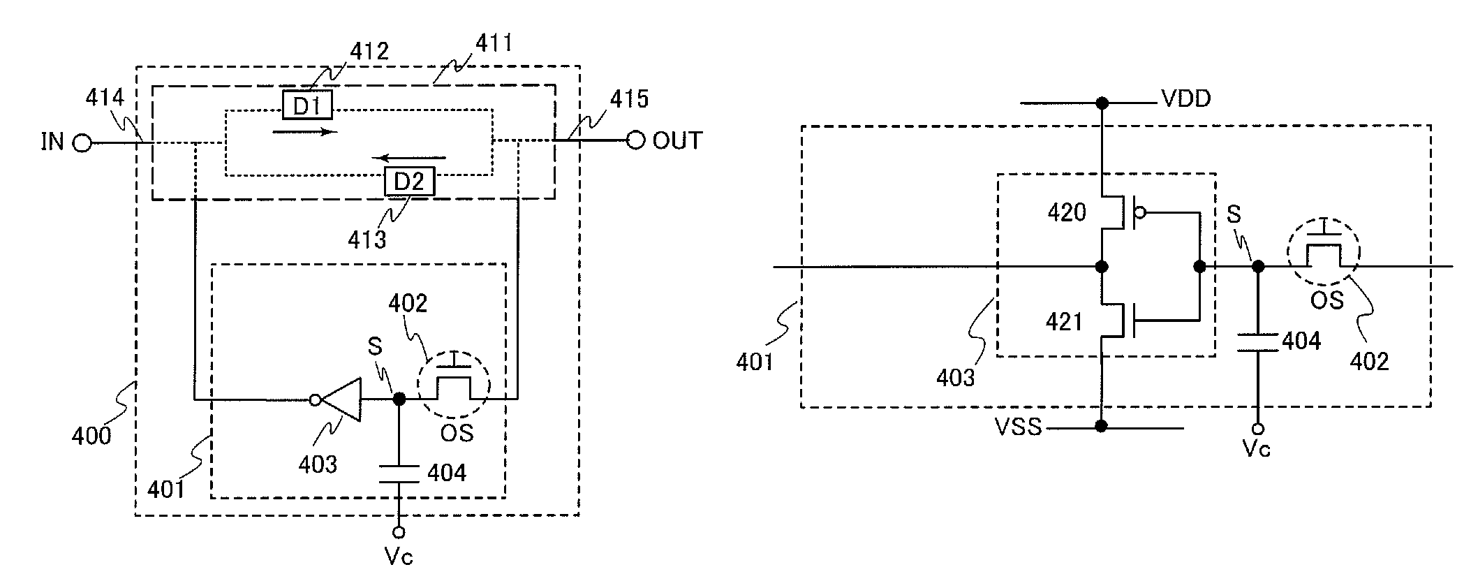
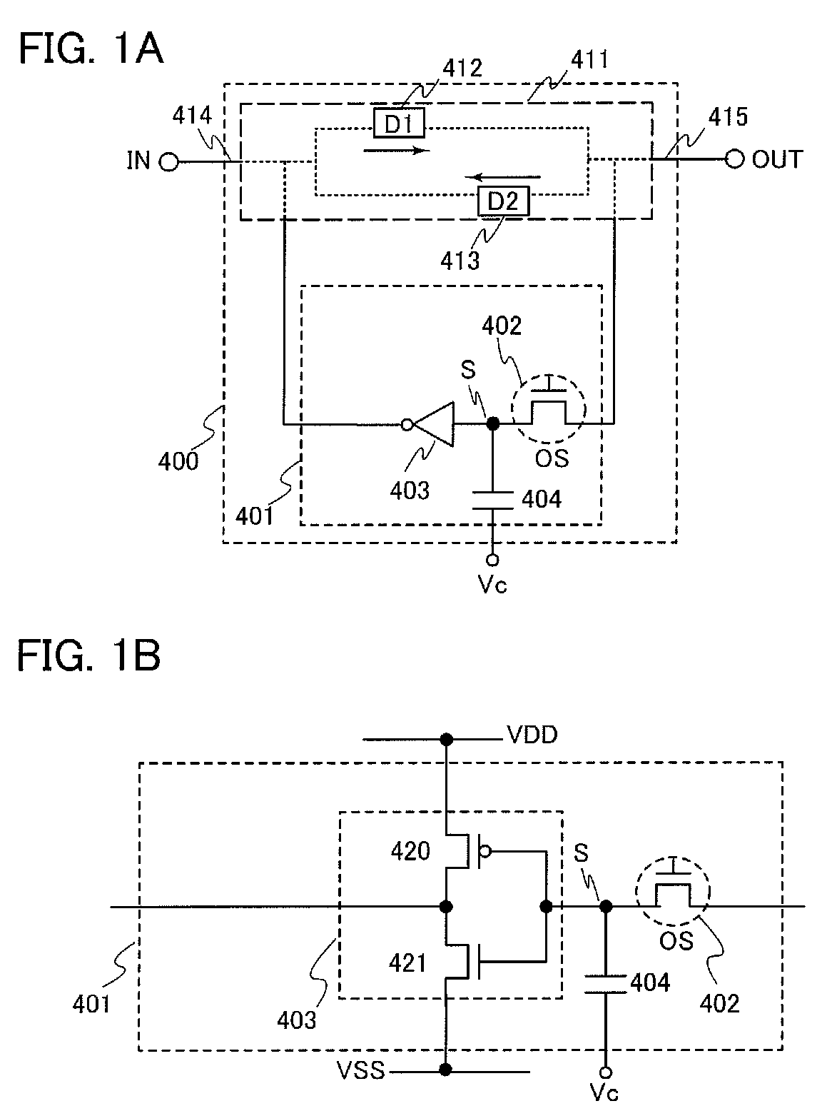
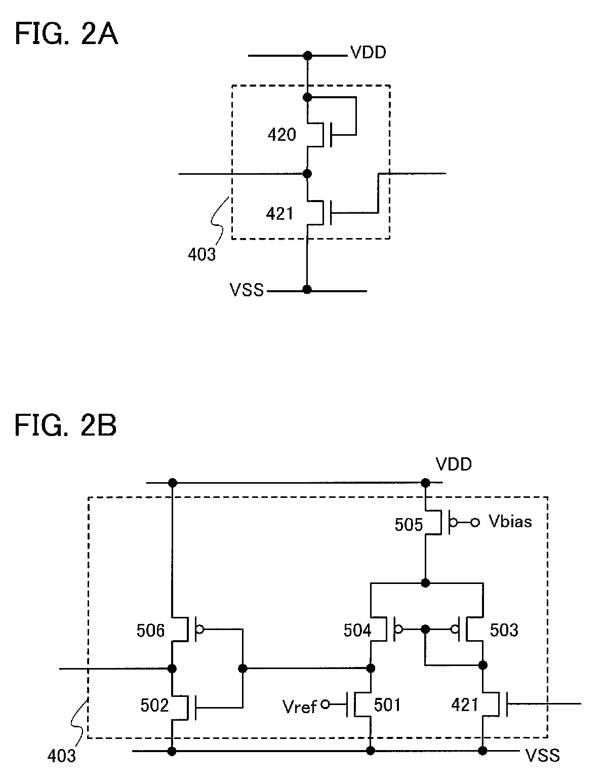
[0050]In this embodiment, an example of a configuration and an operation of a nonvolatile latch circuit which is an embodiment of the invention disclosed herein, a method for manufacturing an element included in the nonvolatile latch circuit, and the like will be described with reference to FIGS. 1A and 1B, FIGS. 2A and 2B, FIGS. 3A and 3B, FIGS. 4A to 4H, FIGS. 5A to 5G, FIGS. 6A to 6D, FIG. 7, FIG. 8, FIGS. 9A and 9B, FIG. 10, FIG. 11, FIG. 12, FIG. 13, FIG. 14, FIG. 15, FIG. 16, and FIG. 17.
[0051]FIG. 1A illustrates a configuration of a nonvolatile latch circuit 400 including a latch portion 411 and a data holding portion 401 for holding data of the latch portion. FIG. 1B illustrates a configuration of the data holding portion 401.
[0052]The nonvolatile latch circuit 400 in FIG. 1A includes the latch portion 411 having a loop structure and the data holding portion 401 for holding data of the latch portion. In the latch portion 411 having a loop structure, an output of a first elem...
embodiment 2
[0200]In this embodiment, another example of a configuration of the nonvolatile latch circuit which is an embodiment of the invention disclosed herein, which is different from the example in FIGS. 1A and 1B, will be described with reference to FIGS. 18A and 18B. FIG. 18A illustrates a configuration of a nonvolatile latch circuit 400 including the latch portion 411 and a data holding portion 401 for holding data of the latch portion. FIG. 18B illustrates a configuration of the data holding portion 401.
[0201]FIGS. 18A and 18B illustrate an example in which the configuration of the data holding portion 401 is different from that in FIGS. 1A and 1B. Specifically, a capacitor (the capacitor 404 in FIGS. 1A and 1B) of the data holding portion 401 is not provided in this example. The other configurations are the same as that of FIGS. 1A and 1B; therefore, description thereof is omitted. The structure of the transistor 402 is similar to that in Embodiment 1.
[0202]In the data holding portion...
embodiment 3
[0211]In this embodiment, an example of a configuration and an operation of the nonvolatile latch circuit which is an embodiment of the invention disclosed herein will be described with reference to FIGS. 19A and 19B and FIGS. 1A and 1B.
[0212]FIG. 19A illustrates a configuration of the nonvolatile latch circuit 400 including the latch portion 411 and the data holding portion 401 for holding data of the latch portion. FIG. 19B illustrates an example of a timing chart of the nonvolatile latch circuit 400.
[0213]FIG. 19A is an example in which the configuration of the latch portion 411 in FIG. 1A is specifically illustrated. FIG. 19A is an example of the configuration of the latch portion 411 in FIG. 1A, where an inverter is used for each of the first element and the second element. The structure of the transistor 402 is similar to that in Embodiment 1.
[0214]The latch portion 411 includes an inverter 412 and an inverter 413. The latch portion 411 has a loop structure in which an output ...
PUM
 Abstract
Description
Claims
Application Information
 - R&D
- Intellectual Property
- Life Sciences
- Materials
- Tech Scout
- Unparalleled Data Quality
- Higher Quality Content
- 60% Fewer Hallucinations
Browse by: Latest US Patents, China's latest patents, Technical Efficacy Thesaurus, Application Domain, Technology Topic, Popular Technical Reports.
© 2025 PatSnap. All rights reserved.Legal|Privacy policy|Modern Slavery Act Transparency Statement|Sitemap|About US| Contact US: help@patsnap.com


