
Liquid crystal display device and driving method thereof

a technology driving method, which is applied in the direction of static indicating device, non-linear optics, instruments, etc., can solve the problems of abnormal output of goa circuit, increase leakage current, and insufficient driving, so as to improve product quality, expand operating temperature range, and increase the operating temperature range of liquid crystal display device

Active Publication Date: 2020-05-28
TCL CHINA STAR OPTOELECTRONICS TECH CO LTD
View PDF0 Cites 0 Cited by
  • Summary
  • Abstract
  • Description
  • Claims
  • Application Information

AI Technical Summary

Benefits of technology

The present invention is about a liquid crystal display device that can operate at a wide range of temperatures and has high quality. The device has two groups of thin film transistors (TFTs) that control the delivery of commands to the display. The TFTs in the first group have wider channels than the TFTs in the second group. When the temperature is too high, the device only activates the TFTs in the second group, and when the temperature is too low, the device only activates the TFTs in the first group. This ensures that the device operates effectively over a wide range of temperatures and improves the quality of the display. The invention also provides a driving method that expands the range of temperatures in which the device operates and improves its quality.

Problems solved by technology

Under a low temperature condition (below −50 degrees Celsius), the current flowing through the TFTs will become smaller, resulting in insufficient driving.
Under a high temperature environment (above 80 degrees Celsius), the current flowing through the TFT increases, and the leakage current increases and the output of the GOA circuit becomes abnormal.
The two are opposite, so the operating temperature range of the existing GOA circuit is very limited.

Method used


Image

  • Liquid crystal display device and driving method thereof
  • Liquid crystal display device and driving method thereof
  • Liquid crystal display device and driving method thereof

Examples


Embodiment Construction

[0048]For better explaining the technical solution and the effect of the present invention, the present invention will be further described in detail with the accompanying drawings and the specific embodiments.

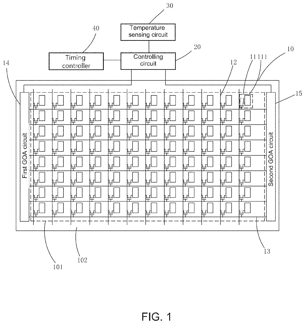
[0049]Please refer to FIG. 1. The present invention provides a liquid crystal display device; comprising a liquid crystal panel 10, a controlling circuit 20 electrically coupled to the liquid crystal panel 10, a temperature sensing circuit 30 electrically coupled to the controlling circuit 20 and a timing controller 40 electrically coupled to the controlling circuit 20.

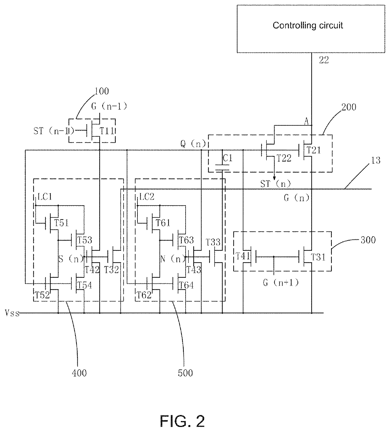
[0050]The liquid crystal panel 10 comprises a plurality of sub pixels 11 arranged in an array, a plurality of data lines 12 respectively coupled to a plurality of columns of sub pixels 11, a plurality of scan lines 13 respectively coupled to a plurality of rows of sub pixels 11; and a first GOA (gate driver on array) circuit 14 and a second GOA (gate driver on array) circuit 15 respectively disposed on both side...


PUM

PropertyMeasurementUnit
temperatureaaaaaaaaaa

Abstract

Provided are a liquid crystal display device and a driving method thereof. A first GOA circuit and a second GOA circuit are provided, and channel widths of thin film transistors in the first GOA circuit are greater than channel widths of thin film transistors in the second GOA circuit. When the ambient temperature is too high, the start signal and the clock signal are only outputted to the second GOA circuit to provide the scan signals. When the ambient temperature is too low, the start signal and the clock signal are only outputted to the first GOA circuit to provide the scan signals to the plurality of scan lines. When the ambient temperature is normal, the start signal and the clock signal are outputted to the first GOA circuit and the second GOA circuit to provide the scan signals to the plurality of scan lines at the same time.

Description

FIELD OF THE INVENTION[0001]The present invention relates to a display technology field, and more particularly to a liquid crystal display device and a driving method thereof.BACKGROUND OF THE INVENTION[0002]The Liquid Crystal Display (LCD) possesses advantages of thin body, power saving and no radiation to be widely used in many application scope, such as LCD TV, mobile phone, personal digital assistant (PDA), digital camera, notebook, laptop, and dominates the flat panel display field.[0003]Most of the liquid crystal displays on the present market are backlight type liquid crystal displays, which comprise a liquid crystal display panel and a backlight module. The working principle of the liquid crystal display panel is that the Liquid Crystal is injected between the Thin Film Transistor Array Substrate (TFT array substrate) and the Color Filter (CF). The light of backlight module is refracted to generate images by applying driving voltages to the two substrates for controlling the...

Claims


Application Information

Patent Timeline
Patent Type & Authority Applications(United States)
IPC IPC(8): G09G3/36
CPCG09G3/3688G09G2320/041G09G3/3677G02F1/13454G09G3/36G09G3/3681G09G2310/0281G09G2310/0286
Inventor XU, XIANGYANG
Owner TCL CHINA STAR OPTOELECTRONICS TECH CO LTD
Learn More