
Continuously insulated wall assembly

a wall assembly and continuous insulation technology, applied in the field of continuous insulation building wall assemblies, can solve the problems of large installation time, laborious and cumbersome installation of wall systems, and numerous drawbacks of wall systems, so as to reduce the number of external wall components, reduce labor intensity, and reduce the weight of wall assemblies

Active Publication Date: 2013-03-19
DOW GLOBAL TECH LLC
View PDF23 Cites 38 Cited by
  • Summary
  • Abstract
  • Description
  • Claims
  • Application Information

AI Technical Summary

Benefits of technology

The present invention is a new type of wall assembly for commercial construction that is better than traditional gypsum-board based walls. It uses a polymer foam layer instead of a separate substrate layer, which makes it stronger and more durable. This new wall assembly is also lighter and more resistant to humid environments than traditional walls. Overall, it is easier to install and more suitable for building construction.

Problems solved by technology

Such a wall system suffers from numerous drawbacks.
Gypsum board is dense, heavy material that makes installation of the wall system labor-intensive and cumbersome.
The wall system requires numerous layers of materials (cavity insulation, gypsum board, water barrier, seam sealing and a thermal insulating barrier) in order to achieve the demanding building code requirements, which in turn require extensive time for installation.
Materials such as gypsum board can also suffer from deterioration if moisture penetrates into the gypsum board, a not-unlikely problem in humid or rainy environments.
Moisture can be particularly problematic in the cavity space when a surface in the cavity space is at a temperature below the dew point of the humidity in the cavity, which results in condensation of the moisture on the cold surface.

Method used


Image

  • Continuously insulated wall assembly
  • Continuously insulated wall assembly

Examples


example

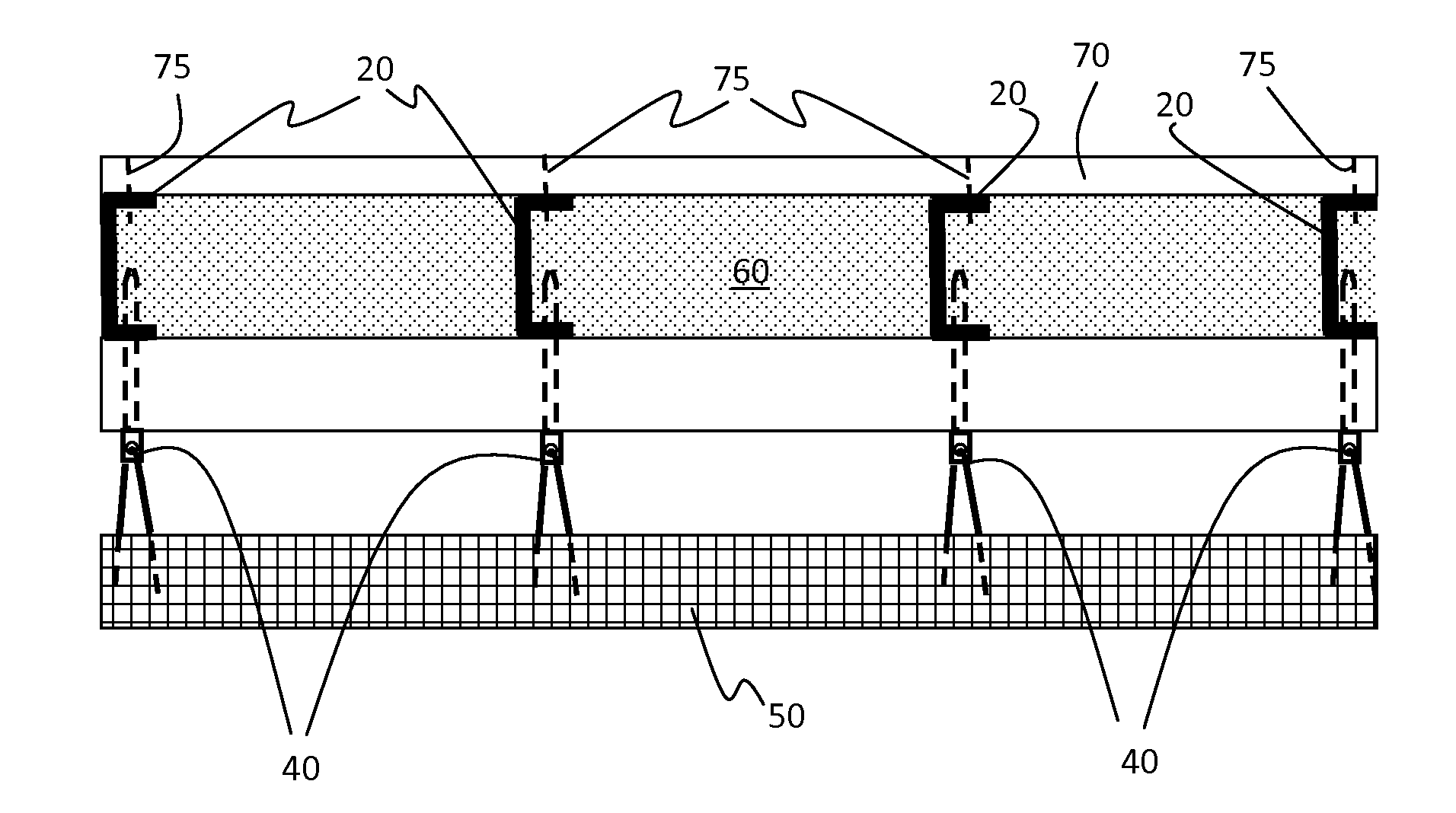
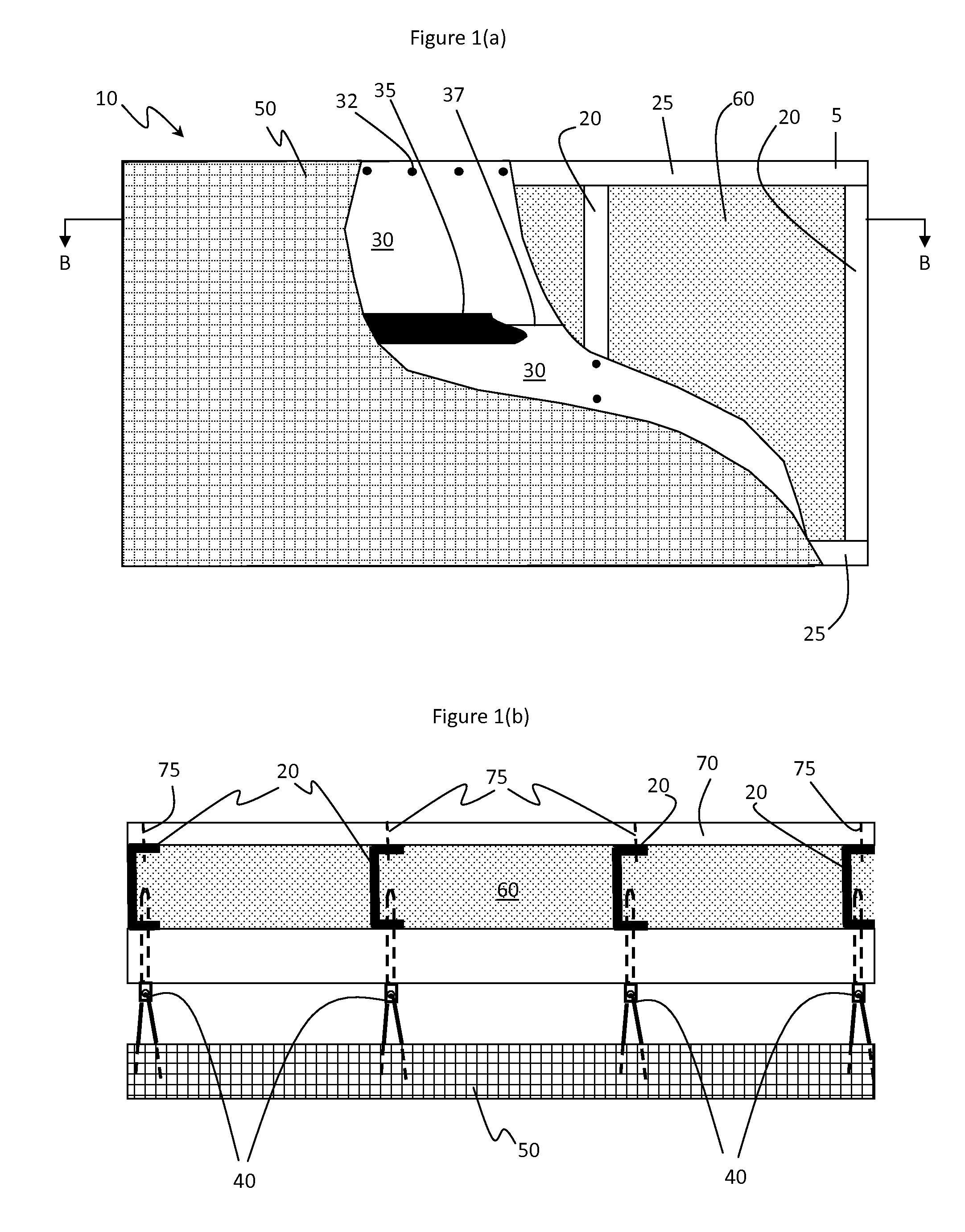
[0056]FIGS. 1(a) and 1(b) provide illustrations of the following structure of the present invention.

[0057]Prepare a 2.4 meter (8 foot) by 2.4 meter (8 foot) support structure, 5, using 2.4 meter (8 foot) long, 9.2 centimeter (3.625 inch) deep 16 gauge steel studs 20 spaced 61 centimeters (2 foot) on center with bracing between studs every 61 centimeters along the 2.4 meter length. Use appropriate top and bottom track materials 25 along the top and bottom of the steel studs 20. For example, use Dietrich DSJ studs with complimentary top and bottom tracks. The support structure 5 has an inside surface and an opposing outside surface spaced apart by the depth of the studs 20.

[0058]Apply two 2.4 meter (8 foot) by 1.2 meter (4 foot) boards of 1.6 centimeter (0.625 inches) thick THERMAX™ ci exterior insulation (THERMAX is a trademark of The Dow Chemical Company) onto the outside surface of the support structure so as to cover the outside surface of the support structure and form a continuo...


PUM


Abstract

Construct a wall assembly by: (a) providing a support structure with spaced apart structural members; (b) affixing a thermally insulating layer of polymeric foam boards to the structural members, the foam boards achieving a Class A rating according to ASTM E-84; (c) covering seams between polymeric foam boards with a sealing tape; (d) affixing a plurality of fasteners through the thermally insulating layer to structural members with the fasteners extending beyond the outside surface of the thermally insulating layer; (e) attaching a façade selected from metal panel, metal-composite-metal panels, fiber reinforced cementitious siding veneer and materials having a thickness of at least 1.9 centimeters (0.75 inches) that qualify as “non-combustible” according to ASTM E136 to the fasteners and within five centimeters of the thermally insulating layer; and desirably (f) applying a spray polyurethane foam material to seal gaps through the thermally insulating layer; the process being free of applying gypsum sheathing layer or wood-based sheathing between structural members and the thermally insulating layer.

Description

CROSS REFERENCE STATEMENT[0001]This application claims the benefit of U.S. Provisional Application No. 61 / 076,174, filed Jun. 27, 2008.BACKGROUND OF THE INVENTION[0002]1. Field of the Invention[0003]The present invention relates to a continuously insulated building wall assembly suitable for use in commercial buildings and a method for assembling such wall assembly.[0004]2. Description of Related Art[0005]Commercial buildings in North America are regulated by numerous building codes. American Society of Heating, Refrigerating and Air-Conditioning Engineers (ASHRAE) standard 90.1-2007 prescribes thermal insulation requirements, which can require continuous insulation as part of a wall structure. National Fire Protection Association (NFPA) standard 285 identifies flame propagation requirements for exterior non-load bearing wall assemblies. American Society for Testing and Materials (ASTM) standard E-331 dictates water barrier property requirements. ASTM E-2357 dictates air barrier pro...

Claims


Application Information

Patent Timeline
Patent Type & Authority Patents(United States)
IPC IPC(8): E04B1/00
CPCE04B2/58E04H5/10E04B1/76E04B2001/2481
Inventor HANSBRO, JEFFREY M.KONTRANOWSKI, MICHAEL J.SCHROER, DANIEL R.TEMPAS, DANIEL A.
Owner DOW GLOBAL TECH LLC
Learn More